What's new
What's new

Enco Mill w/ Variable Speed Head won't run over 1200RPM...and other short stories.

npolanosky

Cast Iron
Joined
Apr 9, 2016
Location
USA, FL
Hi all,

I'm a member of an awesome makerspace called FamiLAB located in Orlando, FL. We've got some older machinery in our metal shop that needs some TLC, especially our '92 HAAS VF-1 and our Enco Knee mill. I'll start another thread for the HAAS stuff, for now this will focus on our sad little bridgeport clone.

First off, I know it's a piece of crap from across the pacific....That's part of why I'm here asking questions! If anyone would like to donate something nicer, we will happily write you a donation receipt and you can write it off on your taxes- We're a 501c3 nonprofit and we can do that. Thanks in advance ;) Past that, it's what we've got so I'm going to work with it and hopefully get some help from the awesome folks here on PM. Be nice, I'm a newly-minted self-taught machinist a la John Saunders- Learning by the seat of my pants, youtube, and LOTS of reading, but not all of the neat tricks and basic fixes are necessarily obvious to me yet :)

Anyway, let's get down to the problems- There are a few that I'd like some pointers on.

1.) The biggest problem we are having is that our spindle won't run over 1200RPM or so in high range, and not more than about 150 in low range. Ours has the (Bridgeport 2J?) variable speed style head as opposed to the step pulley type. When you turn on the spindle and crank the handle, it will speed up or slow down as expected, but once you hit 1200+ it audibly stops speeding up and sometimes "pulses". I'm sure it's something is the transmission and I would have pulled the head already if I knew what I was doing (Or had something to lift it safely with).

Where should I start looking for issues? Easiest way to access the bits inside? There are less access panels than I would like- To me it looks like my only way is to pull off the entire top of the head, which looks heavy to someone without a crane/hoist.

2.) Power quill feed is no worky worky. Wondering if it's related to the abovementioned mayhem in the head. Would be nice to have working, not a priority. I really don't know how to diagnose this one, but following manuals, videos, and intuition I can't get it to so much as twitch, nevermind feed properly.

3.) Feeds on the table and saddle are smooth...most of the time. Sometimes it hits a "rough" spot where all of a sudden the smooth resistance in the leadscrew gets choppy and everything starts making an awful squeaking noise. I've greased, oiled, and adjusted a few things to no avail. Worn out spots on leadscrews? Gibs need adjustment? Something else?

4.) X axis power feed worked when we got the machine, and now appears to have died. It gradually slowed down, reportedly working intermittently when given a boost to start or pressing the rapid button, then quit. Should I pull the motor and clean the brush/commutator assembly, or is it a lost cause? I have nice servomotors I could retrofit in if needed.

5.) Finally, the Z/Quill axis DRO encoder was broken. I think the glass scale is still intact, but the sensor has goop on it and some wires are detached. I'm decent at soldering, but this one could be a challenge. Anyone make (affordable) replacements, or should we continue to go without? Seems like the least critical axis to have a DRO on.


Thanks in advance- I'll probably have a lot more questions, both to figure out how to get this machine running well (Or as well as a 30 year old used, abused, import clone can!) Off to HAASland to figure out a 25 year old ATC alarm code :popcorn:
 

Attachments

  • IMG_20160801_171311525.jpg
    IMG_20160801_171311525.jpg
    96.1 KB · Views: 1,689
The mill wired for the correct voltage? You supplying it with 220-240 and it wired for 440 it ain't gona want to run to speed. There isn't but one place on those style mills that uses grease ,oil everywhere else. Power down feed several places things could be FUBAR! Ya just have to start looking at things,not much help at a distance.
 
1.The "transmission" is a Reeves Drive type system. Two sets of sheeves. One is the drive the other driven as the front set is adjusted the motor set follows. The rpm hangs when there is an interference between the shaft and the floating sheeve. Typical would be a key failure. In the case of the 2Hp Bridgeport the cap screw that holds the key in position could be snapped. The pulsing occurs when the the front set of sheeves is adjusted to an rpm above the 1200/150 range. Pressure is no longer maintained on the belt so it will slip.

The motor has to come off first. The motor drive key is the first place to look for trouble.

If no manual is available get one for a Bridgeport off the web.
http://neme-s.org/Shaper Books/Brid...g Machine Parts Diagrams Series IJ and 2J.htm

http://bridgeport.askmisterscience.com/bridgeportlit.htm#1


2. "no worky worky" is not much to go on.

3. That "squeak" is usually the sloppy fit between the table screw and the nut. It's just wear. Either don't sweat it or adjust the nut. Usually run the table to the right. Use a flashlight to find the adjuster at 3:00 o'clock on the knuckle bracket. Over-adjustment may crack the bracket.

4. Inspect the brushes. It's a dirty hole they live in and they might be sticky.

John
 
The mill wired for the correct voltage? You supplying it with 220-240 and it wired for 440 it ain't gona want to run to speed. There isn't but one place on those style mills that uses grease ,oil everywhere else. Power down feed several places things could be FUBAR! Ya just have to start looking at things,not much help at a distance.

Yep, it's getting 3 phase 230. The speed issue is something mechanical for sure. it has a one-shot oiler with Vactra 2 in it.

1.The "transmission" is a Reeves Drive type system. Two sets of sheeves. One is the drive the other driven as the front set is adjusted the motor set follows. The rpm hangs when there is an interference between the shaft and the floating sheeve. Typical would be a key failure. In the case of the 2Hp Bridgeport the cap screw that holds the key in position could be snapped. The pulsing occurs when the the front set of sheeves is adjusted to an rpm above the 1200/150 range. Pressure is no longer maintained on the belt so it will slip.

The motor has to come off first. The motor drive key is the first place to look for trouble.

2. "no worky worky" is not much to go on.

3. That "squeak" is usually the sloppy fit between the table screw and the nut. It's just wear. Either don't sweat it or adjust the nut. Usually run the table to the right. Use a flashlight to find the adjuster at 3:00 o'clock on the knuckle bracket. Over-adjustment may crack the bracket.

4. Inspect the brushes. It's a dirty hole they live in and they might be sticky.

John

Thanks- I know "no worky worky" was terribly undescriptive,but I don't have much to go on either. Didnt know if there were common problem areas to start at.
Re: motor- The key failure sounds likely and is something I'm definitely comfortable repairing. I'll take a look later today when I can get a few extra hands to lift the motor off.
I'll try adjusting the nut gently- The squeak/slop is pretty bad at times.

No Grease for anything below the head. Does the mill have a one shot oiler and is it working? Should be filled with Vactra #2 or equivalent.
It has one, it has Vactra 2, I think it's working? Will take a closer look.
What brand of DRO? They are not all the same.
JR

It appears to be an Enco DRO as well. Wasn't sure how standard those things are.
 
Motor R&R is 3-5 minutes out and the same to replace. If the task is a struggle with the clock running past 15 minutes take a time out.

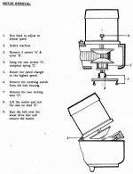
Basic removal: Run the mill to the lowest rpm. Cut the power. Remove the switch from the side of the head. Do not disconnect any wire. Clean the machine table. Use the table to stand on (step ladder is too dangerous). Rotate the turret so the ram is parallel to the table. Remove two motor bolts.
Right now the the belt is at the minor diameter on the motor shaft and the major diameter on the spindle shaft. Turn the rpm selector to the high setting. This lets the top sheeve of the front pulley set to slide up on the shaft. Lean the top of the motor towards the front. This pulls the belt to a smaller diameter on the front sheeves. This generates the slack needed to remove the motor.
One man should be able to extract the motor and with assistance invert it and set it on the table. Watch the slack in the power cord.

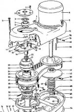
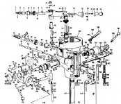
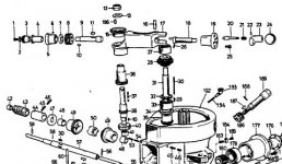
Attached are instructions from the manual and an assembly drawing.
Motor R&R 1of2.jpgMotor R&R 2of2.JPGHead Assembly.JPG
I stopped with the "safety screws" years ago. They are not long enough and the threads strip. When they are used the spring loaded sheeve pushes the belt to a larger running circumference thus eating up usable slack.

Needed is a very good snap ring tool. I use a big pair with a step lock. With the motor inverted one man pushes down to compress the spring thereby reliving the pressure on the snap ring. The second man removes the snap ring. Release the pressure and the spring relaxes.
ezee-pezee
John
 
2. "no worky worky"

Diagnosis, find what does work first. The feed has to be engaged at the spindle. Feed range should be engaged. Look for function such as the shaft is turning at the Forward-Neutral-Reverse pull-push #111 on the front face.
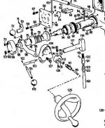
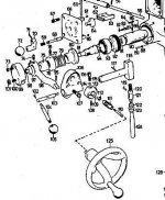
J-Head explode 1.JPGBP Feed 3.JPG

Here is the assembly for pto from the spindle. I have never seen one go bad.
Bridgeport Feed Subassembly.jpg

If #111 is in neutral that explains why there is no feed.
John
 
Progress so far! Motor and top cover removed. This enco mill is a bit different than the bridgeport version, but close enough most of the instructions are accurate. Unfortunately the sheave locking holes are not present, so I had to remove the spring retaining plate and spring to release the motor from the belt and housing. This was less than ideal and the spring flew out and bit my finger. Whoops. Minor injury count +1.

I suspect that plate as part of the problem actually- The bolt holding it in was pretty loose to begin with, so it may not have been squeezing the sheaves together enough to maintain tension at high speeds. In addition, the wear pattern on the sheaves indicates that the motor side is the side that was slipping, and the spindle side is operating properly.

Going to dig deeper to continue familiarizing myself with the mill and see what's up with the power quill feed. I don't get any rotary motion on the #111 shaft, and pushing or pulling it has no effect.
 

Attachments

  • IMG_20160803_153805655.jpg
    IMG_20160803_153805655.jpg
    94.8 KB · Views: 810
Progress again!
Opened up the assembly marked below, and the little gear selector slider was misaligned! Put it back in place and we have shaft rotation!
Still need to figure out why the quill isn't moving down, but that's a step in the right direction.
 

Attachments

  • quill feed.jpg
    quill feed.jpg
    74.9 KB · Views: 3,177
What mechanism actually moves the quill downwards? Everything seems to be working from the PTO to the feed selection gearbox to the fwd/neutral/rev lever, but there's a disconnect between there and the quill.
 
Woo! Got everything back together except the motor. Taking 5 to recover from all that lifting. Cast iron is HEAVY without a crane.
 
I suspect that plate as part of the problem actually- The bolt holding it in was pretty loose to begin with, so it may not have been squeezing the sheaves together enough to maintain tension at high speeds. In addition, the wear pattern on the sheaves indicates that the motor side is the side that was slipping, and the spindle side is operating properly.

The pressure from the spring forces the floating sheave toward the fixed sheave. As the floating sheave moves closer rpm increases as the belt approaches the periphery of the sheaves. If the floating sheave cannot move all the way up the shaft maximum rpm will not happen.
Probable cause:
Damaged key/key retainer capscrew is causing sliding interference.
Spring has lost tension. I did replace a couple of springs. Comparing new to old there was a height difference.

Remove the belt, slide the sheaves together till they kiss. The belt should wrap around between the sheaves and be just flush with the outer edge of the sheaves.

What bolt?? Was there a snap ring/circlip? I see the snap ring groove on the motor shaft.
Up to five photos can be added per post. Close up shots are better than the 'big picture'.
 
What mechanism actually moves the quill downwards? Everything seems to be working from the PTO to the feed selection gearbox to the fwd/neutral/rev lever, but there's a disconnect between there and the quill.

This gets a little easier with the mill running but here is a check if the mill has the handwheel mount as in the first diagram. Moving the selector rod thru forward-neutral-reverse while rotating the handwheel will move the quill up or down.
BP Feed 3.JPG
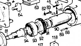
The quill is driven via the worm #43 and worm wheel #92 and there is an overload clutch. Avoid taking the clutch assembly apart or changing the setting. I've set them up but it is something I can do rather than explain.
Bridgeport Feed Subassembly.jpgBP4.JPGBP3.JPG
The rack on the back of the quill is driven by gear #180 and that is keyed to the shaft #166 by key #11. This is also called key #167 depending upon which Bridgeport manual one has. If the quill moves up and down normally with the handle on the right side of the head then this is not the problem.
The worm wheel #92 is keyed to shaft #166.
The key will not fit thru sleeve #91 and has to be inserted from the left hand side.
There is no reason for this key to be dislodged or missing unless shaft #166 has been removed at some time.
Sleeve #90 is held in position by a set screw with a dog above it(two set screws) and it's location is critical so put the hammer away and do not beat on anything:D
 
Last edited:
Ok, so I'm in a real pickle here. This is the enco version without the sheave locking screws on the plate at the end of the motor shaft. I had to remove the spring to get the motor out, and now I'm not quite sure how to compress the spring safely to reinstall the motor! Ideas?
 
Close up photos of the parts would be helpful.

Did you do this from post #15?
"Remove the belt, slide the sheaves together till they kiss. The belt should wrap around between the sheaves and be just flush with the outer edge of the sheaves."
If the belt fits deeper between the sheaves it is either worn or the incorrect belt width.
Of course this is only possible when the cover is removed.

"This is the enco version without the sheave locking screws on the plate at the end of the motor shaft."
Do you mean the two cap screws that are installed to hold the sheave back against the spring during installation? After the belt and motor the cap screws are removed. I stopped doing this years ago even tho I had a pair of extra long capscrews for the job.

Here is an assembly diagram depicting the motor sheaves, spring, spring collar(retainer plate), and circlip.
Motor Shaft Assembly.JPG
If you have the retainer plate and the circlip do this........
Drop the table lower. Put the spring in place followed by the retainer plate orientated so the key is aligned with the keyway.
With two hands push down on the retainer till the plate clears the snap ring groove. The helper with the snap ring pliers guides the circlip into place. Release pressure on the retainer. **Verify that the circlip is seated correctly!

Motor Installation:
First go up on top and pull all the belt slack toward the motor sheave area.
Get in position with the motor over the opening. Lower the assembly into the hole until the fixed sheave just clears the opening. Keeping everything vertical move the assembly towards the spindle sheaves. At this time it should be possible to rest the left side of the motor flange on the top of the cover near the rpm adjustment screw. Tilt the motor clockwise to the right while resting the edge on the cover. Reach in the cavity and slip the belt in between the sheaves. It should be just enough to get it started. Force the motor assembly back to vertical and move the assembly to the right. The belt should spred the sheaves apart.

New belts that are really stiff need a little more free play and the speed adjuster is in the way so I just remove the locknut and screw the adjuster all the way in. Before doing that measure the height of the threads, or count the threads, so the adjuster can be reset.
Sometimes the varidiscs have to be rotated so the belt walks into place.

Remember to reset the variable speed selector till there is some pressure on the spindle sheaves before startup else the slack is going to make it jump.
 
I have a similar machine - did you ever get the quill feed working?
My handle will spin, but won't engage the quill.
 
I have a similar machine - did you ever get the quill feed working?
My handle will spin, but won't engage the quill.

You may not get an answer since this thread is four years old. :)

Sadly, MSC bought Enco about the time that this thread was made and they killed the brand so that there are no more parts and manuals AFAIK.

I used to buy things like end mills, sanding discs, belts and way oil from Enco and they were excellent since they would ship in one or two days from a warehouse in Nevada. They had good prices and were very reliable.

Bridgeport manuals are available online from the website. I used one to refurbish my big Webb mill.

Even though this is an old thread, there is some good advice above.


Back
Top