What's new
What's new

Excello 602 tear down

Stronghold

Aluminum
Joined
Jan 5, 2015
Location
Jefferson City, MO
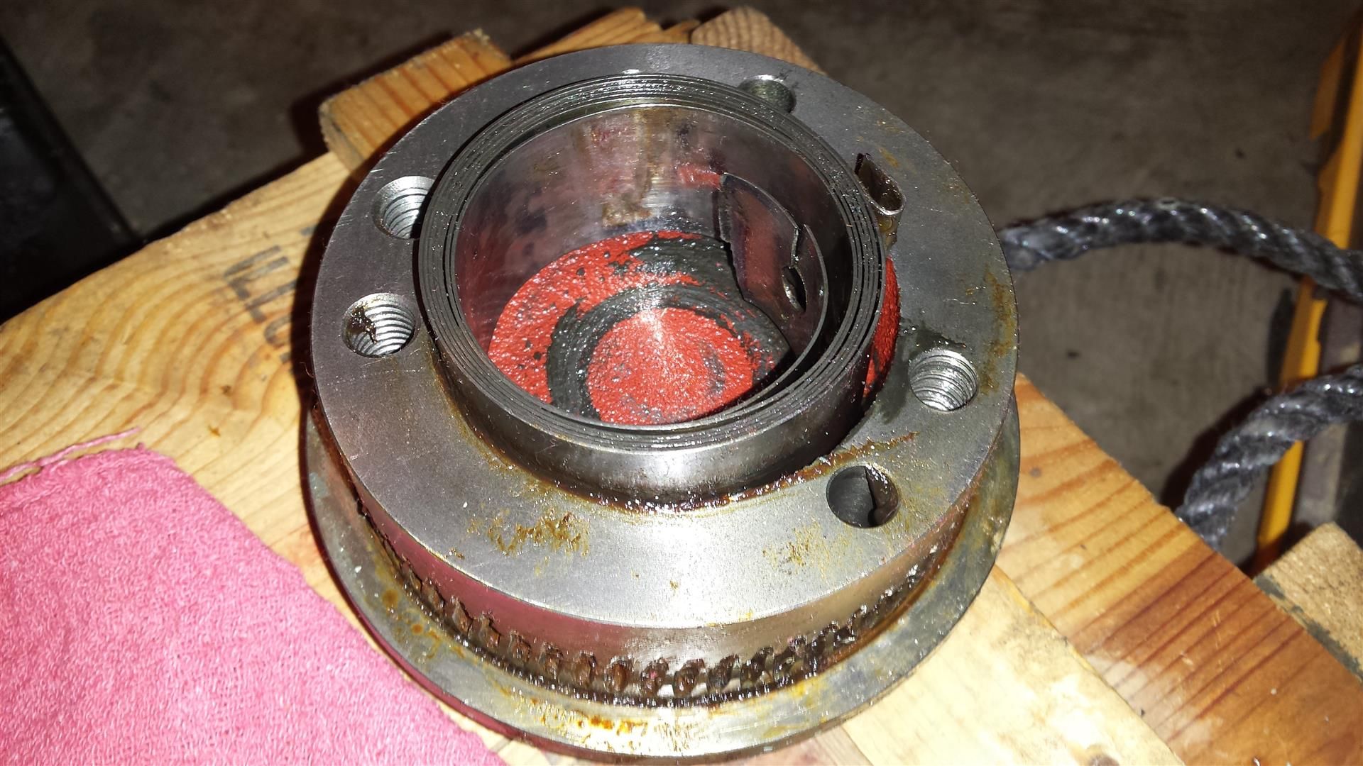
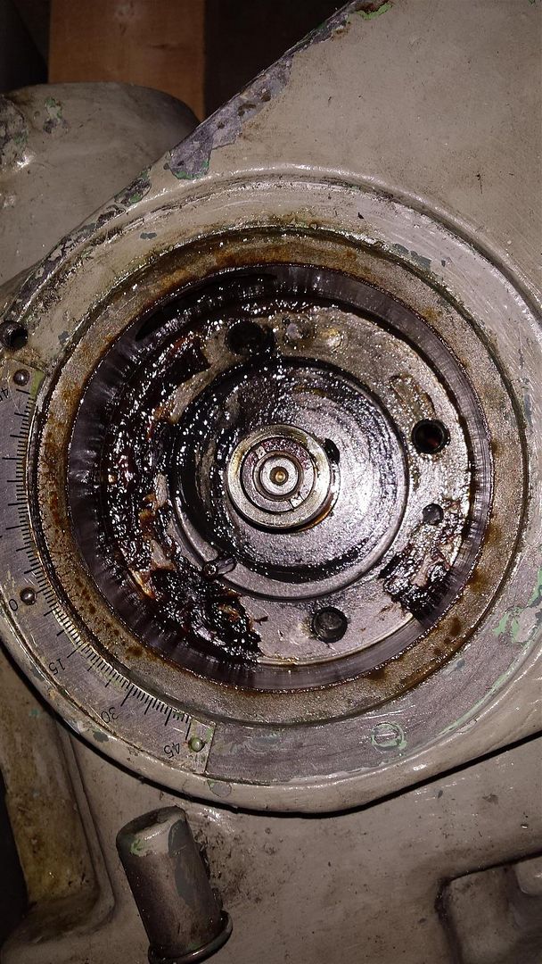
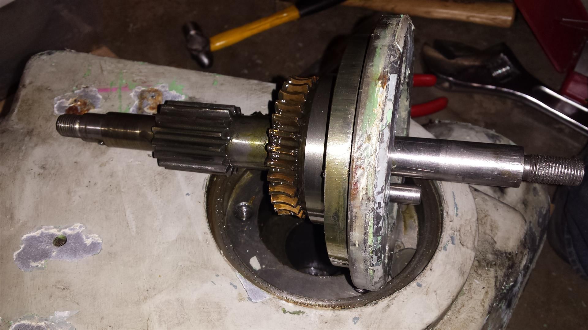
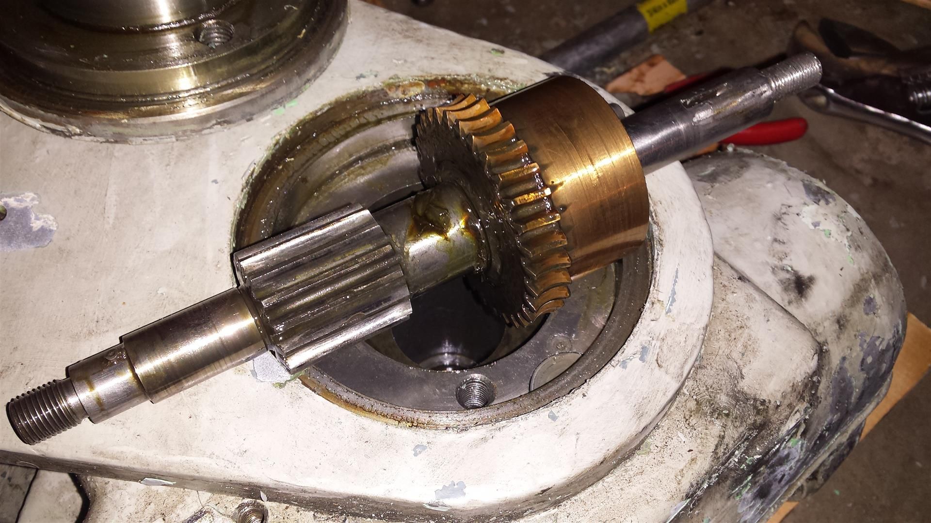
Hello everyone, this is my first personal mill and would like some help in its disassembly. I've removed the head and was able to remove the upper portion (motor housing) and middle portion (gearbox) of the head. Now I'm left with the lower section of the head that houses the gears that drive the fine down feed. I opened up the back where the gears are located and was able to remove them (along with a lifetime supply of grease that came out of it). Now all that's left is the quill lever gear and the knuckle/yoke that the head pivots up and down on.

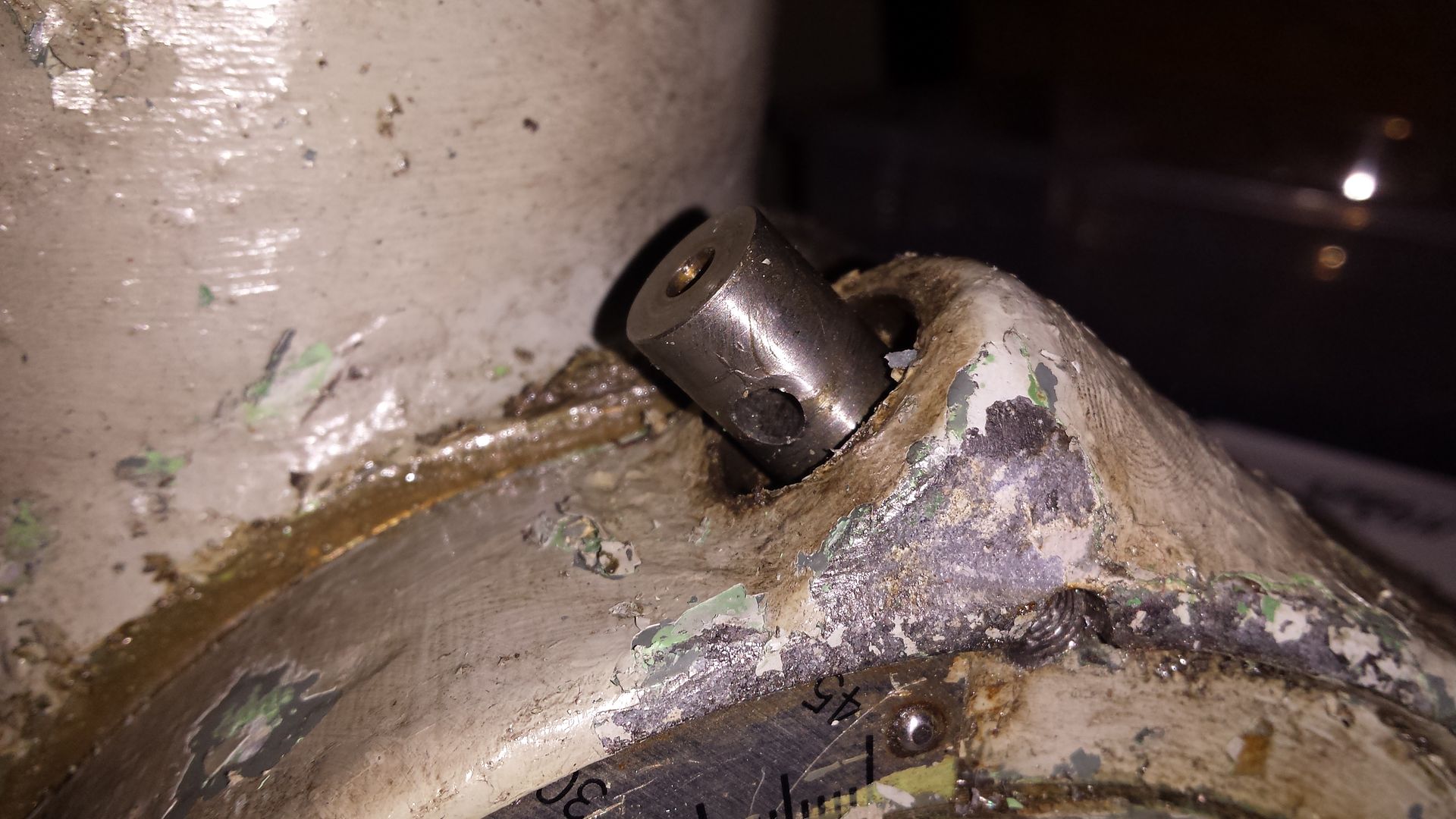
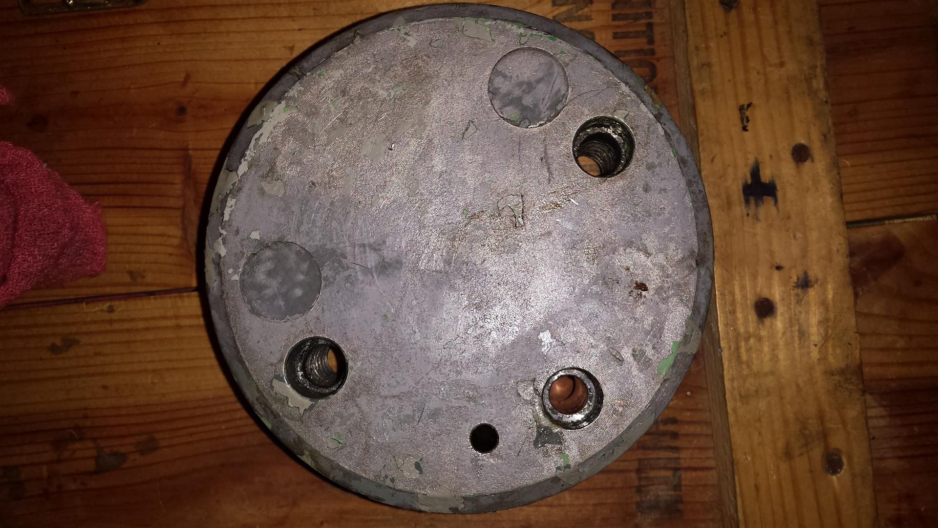
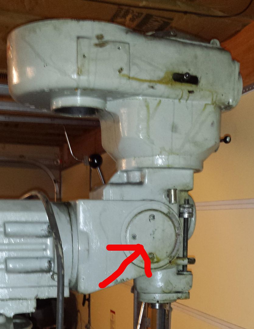
The pictured cap seems to be what's holding up the progress, but I can't figure out how to remove it. I've already removed the three bolts but can't find a seam to pry it off. I know that a few of you have broken these down before in the past so I'm hoping some of you will have the answers. I'm sure I'll have more questions as I progress through this.

Any and all suggestions would be greatly appreciated.

221cec68-2f44-4d32-a7c8-bc04706239c0_zps1c403d25.jpg
 
Try this
http://igor.chudov.com/manuals/Excello-602-Mill-Manual.pdf

IIRC, the adjustment screw hold it in.
JR

Thanks for the reply. I have copies of the two manuals that are available, but my machine is older than those and a few things are different, like the cover I'm trying to remove. From what I've seen in those manuals and from talking to others there are two holes in the newer versions that allow easy removal. I'm contemplating just going ahead and make those same threaded holes, but I'm still on the fence.
 
If you look at page 19, section D-D, it show that plate with the nod adjusting screw going on the bottom side. You have to pull the adjusting screw BEFORE you pull the plate. You can put all the holes you want into it, but it won't come out until the adjusting screw is removed.
JR
 
If you look at page 19, section D-D, it show that plate with the nod adjusting screw going on the bottom side. You have to pull the adjusting screw BEFORE you pull the plate. You can put all the holes you want into it, but it won't come out until the adjusting screw is removed.
JR

Thanks again. I see what you're talking about from the manual, but now I'm getting conflicting information. I messaged a guy on another forum who had recently broken down his Excello and he said that the cover needs to come off in order to remove the adjustment gear. I just came back from checking out my machine and the adjustment screw can only come out the front, and only has a single pin holding the head that rotates the gear. I removed the pin and head but I can't see anything else under the head that will allow the removal of the gear. I guess I'll just have to keep playing with it. Again, I appreciate the help. It's unfortunate that there's such little information out there on these.
 
If you look at page 19, section D-D, it show that plate with the nod adjusting screw going on the bottom side. You have to pull the adjusting screw BEFORE you pull the plate. You can put all the holes you want into it, but it won't come out until the adjusting screw is removed.
JR

I agree with JR. Take it out. i remember that is a real pain to get off. i would also scrape off the paint on the cover as it looks like there might be some tapered pins there too. If those pin are in tight they can hold it in super tight too. You may have to drill and tape the pins and use a slide hammer to pull them out. Or use a bushing and a long screw and flat washer and use that t pull out the pins too. The print is a bit hard to see, but it sure looks like the pinion needs to come out. Can't hurt to remove it. Better safe then sorry. It may have never been removed since new . I looked again and I am sure there are some pins there too. Scrape off the paint and I bet there are 2. You maybe right and have to drill and tap some holes in the plate too and use a slide hammer on it too. Rich
 
Thanks again, gents. I went ahead and chiseled off many layers of really hard paint that did expose a pin and a set screw that I didn't notice before. I removed both and now it seems the adjustment gear is free to be removed from the front. The problem is that it's in there tight. Anyone have any suggestions on how to go about pulling this out? I'll take a picture and post it here in a minute to show what I'm dealing with.
 
You should put the bolts back in and lock it and just screw it out. I was thinking that you might be able to either tap the clearance hole of the cap screws holes and bolt on a flat bar to the cover so you can grab it with both hands and wiggle it loose. You can still try the slide hammer idea too... i am glad we are able to help. Rich

PS: It looks like you can now see the degree graduations better under that old paint :-)
 
I recently purchased a 602. I havent torn it down but I did replace the upper spindle bearing and I can help with various measurements ect if needed.
 
Gentlemen, thank you all once again for your help. The adjustment screw indeed needed to be removed first, which baffles me as to why two people said they removed the cover first on theirs. I was trying to unscrew the adjustment screw with no luck, it just kept spinning. So I while I was rotating the knuckle around I saw an extra hole on the other side of the plate that wasn't like the others. I was able to install a bolt into the hole which put pressure on the mating gear, this allowed the adjustment screw to turn out of the hole. Also, there was no need for me to drill extra holes in my cover plate, because the existing holes had threads in the upper portion that were covered in paint. This allowed me to install two bolts into the holes which put pressure on the head and pushed the cover plate straight up and off the knuckle. At that point the quill pinion was exposed on the other side and the reason it couldn't be removed: there was a set screw keeping it from sliding out. Once that screw was removed the gear easily slide out and the cover plate on the other side popped out without issue. There were a few other little parts still in the head but they all were easily removed when the knuckle was separated from the head. Again, I'll be making a large photo journal of all of this once I'm done so others can benefit.

Also, what's strange is that the cover plate has two extra holes that are covered with these metal plugs. There's nothing that screws into them on the other side so they're pretty much worthless. I just found that odd. You can see them in the following picture as the two large circles.

20150110_190710_zpsbc3ff1ab.jpg

20150110_190538_zps6ad35f4c.jpg

20150110_191140_zps2a403862.jpg

20150110_194047_zps53c44ef8.jpg

20150110_194146_zpsfbf4f607.jpg
 
Also, what's strange is that the cover plate has two extra holes that are covered with these metal plugs. There's nothing that screws into them on the other side so they're pretty much worthless. I just found that odd. You can see them in the following picture as the two large circles.

Some earlier models made use of a 3 capscrew BCD on the nod where the screws were equidistant. The plugs cover those equidistant holes and utilize holes that were made after. I will speculate that the Excello factory here in London, Ontario, had many of the early plates already made and utilized them with this small modification.
 
Some earlier models made use of a 3 capscrew BCD on the nod where the screws were equidistant. The plugs cover those equidistant holes and utilize holes that were made after. I will speculate that the Excello factory here in London, Ontario, had many of the early plates already made and utilized them with this small modification.

Thanks for the info. Forgive my ignorance, but I'm not familiar with what BCD stands for. Would you happen to have an idea as to the vintage of this particular 602? From what I've seen, the horizontal spindle brake was an earlier design, but since there's so little information on the net about these I have no idea about what year this was made.
 
BCD = bolt circle diameter. Just referring to the 3 bolts on the nod.

There seems to be 3 distinct types of Excello. They vary in the base castings and head design, as shown below in some google image photos. The last, B&W photo is from the 602 page on Tony's website.

1. Base casting has radii on each side where it meets the foot of the machine. E-Cell-O is spelled on the head. Spindle brake is vertical cam-type, in that you pull the lever up to horizontal (sticks out away from head) to lock, or push forward/back along the head to momentarily brake. This particular machine has an incorrect X-feed, as the XLO versions were attached to the carriage and not the table. They had heavy motors w/belt drives, and something like a quick-change gear box (in both size and heft) on the front actuated by a lever & spring-loaded pawl. The motor runs continuously and the feed is engaged with a clutch.

A2752_12.jpg

2. This style of machine has plain base castings, but angular not round, and what looks like an earlier motor than the above. Ex-Cell-O emblem on the ram, not a cast depression like the above. I have never seen a machine like the above in Canada, but have seen this style.. I don't know the chronology of these styles- if anyone does, please enlighten inquiring minds!

DSCN9927_zps97ce36ff.jpg

3. These are the machines I'm most familiar with. I've seen more of these in Canada than the above. This version has scallops on both the ram and the base casting, Ex-Cell-O emblem on the ram and XLO cast into the front of the head. You can see the equidistant 3-bolt circle on the nod cover. IMO, these are the oldest of the 3 shown here. Dated at before the late 1970's for all the machines shown here. I'll have to check the XLO I have in the shop- I think it's a combination of photo 2 & 3. I'm glad you're taking care of yours- they're excellent machines. If you can get one with the NTMB-40 spindle taper, :cloud9:

img0.jpg
 
BCD = bolt circle diameter. Just referring to the 3 bolts on the nod.

There seems to be 3 distinct types of Excello. They vary in the base castings and head design, as shown below in some google image photos. The last, B&W photo is from the 602 page on Tony's website.

1. Base casting has radii on each side where it meets the foot of the machine. E-Cell-O is spelled on the head. Spindle brake is vertical cam-type, in that you pull the lever up to horizontal (sticks out away from head) to lock, or push forward/back along the head to momentarily brake. This particular machine has an incorrect X-feed, as the XLO versions were attached to the carriage and not the table. They had heavy motors w/belt drives, and something like a quick-change gear box (in both size and heft) on the front actuated by a lever & spring-loaded pawl. The motor runs continuously and the feed is engaged with a clutch.

View attachment 126698

2. This style of machine has plain base castings, but angular not round, and what looks like an earlier motor than the above. Ex-Cell-O emblem on the ram, not a cast depression like the above. I have never seen a machine like the above in Canada, but have seen this style.. I don't know the chronology of these styles- if anyone does, please enlighten inquiring minds!

View attachment 126699

3. These are the machines I'm most familiar with. I've seen more of these in Canada than the above. This version has scallops on both the ram and the base casting, Ex-Cell-O emblem on the ram and XLO cast into the front of the head. You can see the equidistant 3-bolt circle on the nod cover. IMO, these are the oldest of the 3 shown here. Dated at before the late 1970's for all the machines shown here. I'll have to check the XLO I have in the shop- I think it's a combination of photo 2 & 3. I'm glad you're taking care of yours- they're excellent machines. If you can get one with the NTMB-40 spindle taper, :cloud9:

View attachment 126700

Thanks for the info! Mine is combo of #2 and #3 with the ball crank handles and even the same Bijur oiler.

img2_zps9760d3ed.gif
 
I recently purchased a 602. I havent torn it down but I did replace the upper spindle bearing and I can help with various measurements ect if needed.

Have you disassembled yet? I'm in the process of refurbishing an excello 602 and have come to a little problem, I can't get the head separated from the ram. Do you have any suggestions? I took the worm out of the ram and removed the 6 bolts holding it together, but it still won't separate. I shined a flashlight down the ram and I see a pin in the lower left corner. Do I need to remove that pin first? It seems impractical to have to remove it from 4 feet away

IMG_20181013_144337785.jpg
 
Looking to get information on the brake lever for this old style of excello 602, I have the same style of brake as you which differs from the cam lock style on the majority of cellos. Is the brake lever on the excello with rectangular cutout just a threaded rod? I need to replace this brake lever. Any information would be greatly appreciated thanks.


Back
Top