What's new
What's new

Hardinge TFB + electronic lead screw = any good?

Frigzy

Aluminum
Joined
Apr 26, 2018
It seems like the only way to get a Hardinge HLV is to create an alternate universe where I already have a HLV :)

Meanwhile, I see TFB-s are going for much lower prices. If I get it right - it's basically the same lathe minus threading capabilities (i.e. threading lead screw and a gearbox).

I see some people do electronic lead screw mod to their lathes. I wonder if it's a viable option to buy a TFB and add an electronic lead screw to it. I'm an electrical/firmware engineer, so electronic part of it should be straightforward. Mechanical part is challenging though. I see a TFB has a smooth rod in place of a lead screw. What is that for? Can it be easily retrofitted with, say, ball screw?

Thanks!
 
The rod under the bed of aTFB-H lathe has four dovetailed flutes. Each flute has an adjustable stop numbered from 1 to 4. The shaft is rotated in 90 degree intervals with a ratcheting lever. The stops were meant to be used with the four position turret tool post that can replace the compound slide. Hardinge also made a four position cross slide stop with dial indicator. These stops and the tool post could be used for small batch production jobs. Such work might lead to a worn-out bed/carriage interface, so a cheap TFB-H might be worn out.

The only carriage feed on the TFB-H is the rack and pinion. It would be a neat trick to add a carriage feed screw and half nut device that is driven by a servo and timed to the main spindle. Can you devise a half nut for a ball screw? That would be a tricky design job indeed.

Larry
 
The only carriage feed on the TFB-H is the rack and pinion. It would be a neat trick to add a carriage feed screw and half nut device that is driven by a servo and timed to the main spindle. Can you devise a half nut for a ball screw? That would be a tricky design job indeed.

Larry

I don't think you'd need to do a true "half nut", but you would need some sort of connection from carriage to ball screw nut that could be entirely disconnected with a flip plate or some other coupler. And perhaps one could replace the Z stop rod with a ball screw, but not having a TFB at hand to review I can't confirm.

Another possibility is a permanently coupled ball screw with a electronic handwheel to replace the regular carriage wheel. You'll loses "feel", but a lot of newer CNC bed mills and the like are doing this.
 
(Milland types faster than I do. And it's really only 11:15 here. I don't know why it's posted tomorrow)

If the lead screw were electronically driven, all you would have to do to "open" the half nuts would be to stop the rotation of the screw. It would have a lot of interesting implications. Since you know very accurately where the tool is by the number of rotations of the ball screw, an automatic stop at a shoulder would be very simple. Returning to the start of the thread could be automatic as well.

Operating process

After setting the desired threads per inch (or metric pitch):

1. Manually move the threading tool to the start of the thread. Press button 1.
2. Manually move the threading tool to the end of the thread. Press button 2.
3. Press button 3 to return the tool to the start of the thread.
4. Set the cross slide, feed the compound, press button 4. The lathes threads to the location set with button 2 and stops.
5. Back the cross slide out press button 3. The lathe returns to the location set with button 1.
6. Go back to step 4 until you are done.

No watching the thread dial going around, no panic as the tool threads toward a shoulder. Multiple start threads would be a breeze. No transposing gears for english/metric. Thread at high speed for better finish.

It wouldn't have to be limited to threading either. Any feature that has a start and a stop could be done, based on the accuracy of setting the tool locations. Sort of an automatic power feed.

You'd have to replace the hand wheel on the carriage with an encoder of some type for normal lathe operation. Or use a ball screw that could be back-driven.
 
Another possibility is a permanently coupled ball screw with a electronic handwheel to replace the regular carriage wheel.
You'd have to replace the hand wheel on the carriage with an encoder of some type for normal lathe operation.
That's exactly what I'm thinking about. I see BabinMachineTool does just that with their "semi-cnc" HLV retrofit.

The only brainer is: how difficult would it be to replace a smooth rod with a ball screw in a TFB. I would assume that Hardinge used the same parts/castings for both lathes, so all the required openings/holes are there.
 
(Milland types faster than I do.)

First time that's ever happened!! ;)

This is a subject of great interest to me, as I plan on doing a similar conversion (but with a X control too for essentially full CNC capability) to some older lathes I have.

Frigzy, if you're willing to post a build thread on your efforts I'd guess a number of people would follow it.
 
Ok. All what I need now is to find a decent TFB which may pose a challenge. Thank you everybody for accelerating the procedure of depriving my family budget of a chunk of money :-)
 
That is a 1950-1960 TFB. One of the many differences from the redesigned 1960 TFB-H is the compound rest retracting mechanism. On the old model, the retract lever rotates around the feed screw axis, as shown in the eBay listing. On the new model, the lever is on top and rotates around an axis at 90 degrees to the feed screw.

Yesterday in your WTB ad, I asked if you know the difference between the old and new models. There is more to it than bed width. I always assume the Hardinge engineers made those changes to solve problems with the old design.

Larry
 
Could please anyone take a look at this lot Hardinge Lathe TFB Super Precision 22V - 3 phase | eBay ?
It looks ok, but a tool retraction lever is not there. There is something weird going on with the compound rest.

The price I associate with HLV's is in the $1000 to $5000 range. So the difference in money is not worth the work.

Unless you think this will be a fun project. It looks fun to me except for one thing. You make modifications
to the metal parts on the TFB but eventually never get the project to work correctly. You got to live with the
mistake, and it may not be easy to sell off because of the damage.

For threading Hardinge put a straight bar through the lower part of the carriage which have adjustable stops. The bar is located on the right side
by that bracket that holds the gear rod. Except in the add picture the bracket is shorter than usual to a HLV. The stop on the
left side is necessary for thread cutting and I use it all the time.
 
For threading Hardinge put a straight bar through the lower part of the carriage which have adjustable stops.
Does that system engages a spindle brake and stops the spindle?
That might be doable with an electronic lead screw. Micro-controller would just issue a command to a spindle VFD to stop and to the brake to engage. An operator would just need to press a button in a position where he wants a lathe to stop.

The rod moves slightly right or left as you would move the upper handle on a machine built for doing threads.
 
The price I associate with HLV's is in the $1000 to $5000 range. So the difference in money is not worth the work.

Unless you think this will be a fun project. It looks fun to me except for one thing. You make modifications
to the metal parts on the TFB but eventually never get the project to work correctly. You got to live with the
mistake, and it may not be easy to sell off because of the damage.

For threading Hardinge put a straight bar through the lower part of the carriage which have adjustable stops. The bar is located on the right side
by that bracket that holds the gear rod. Except in the add picture the bracket is shorter than usual to a HLV. The stop on the
left side is necessary for thread cutting and I use it all the time.


Are you really seeing used HLV's for as low as a grand?
I keep seeing them in the $7000 to $25,000 range, used, with most of them up around 20k.
right now, on ebay, the cheapest one is $7500.
 
Does that system engages a spindle brake and stops the spindle?

Short answer is no. Only the lead screw and threading train stop; the spindle continues to spin. A dog clutch at the beginning of the threading gear train is used to start, stop and reverse the lead screw at threading speeds. The stop point is selected by setting a stop collar on the threading control rod at the bottom of the carriage. In use, the carriage advances to the stop point then mechanically disengages the dog clutch. In my experience, the stop point usually repeats to within a thou or two, assuming the threading speed is not changed significantly after set-up. Once the carriage stops, the tool is withdrawn using the top slide quick retract mechanism, the lead screw reversed returning to the start position, top slide advanced and the procedure repeated. Single point threads can be very quickly cut from start to finish without stopping the spindle. Note that Hardinge used the same reversing dog clutch threading concept on their tool room lathes from 1939 until production was discontinued about 2008. Their were several improvements in design over the years but the basic concept remained unchanged.

I personally doubt that a VFD driven TFB spindle could be consistently braked a achieve reliably precise tool stop positions.

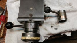
To elaborate on Larry's post about the quick retract mechanism for the TFB/HLV (narrow bed) made fro 1950-1960, here is a close up. The handle operates a sleeve which has a tapered helical 3 tpi groove containing a hardened key. 135 degrees of handle rotation withdraws the top slide .125. To the right is shown the internal parts: the rotating sleeve with groove, key and key retaining screw. In my experience, the small key size and relatively small size of the tapered dog point on the screw were the significant weak points of this design. Unless well maintained and lubricated, the groove may wear unevenly. Or the dog point would break off the screw since it counteracts the vector of the tool cutting forces parallel to the top slide. In at least one case I have seen, the small hardened key broke in the middle, leading to significant chewing up of the groove flanks. Shown in the groove is a replacement key I made out of hard bronze which more than doubles the key contact area but does not entirely solve the small screw size. I recently tooled up to make the pictured repair if anyone wishes more details.
Jim

1114181515.jpg
 
Short answer is no. Only the lead screw and threading train stop; the spindle continues to spin.
Thank you for sharing your knowledge at such a detailed, thorough way.

So it's a carriage stop - not a spindle stop. I somehow thought that a Hardinge has some magic way to cut a thread right into a shoulder without any relief groove. From what you're saying, that seems to be not a case.
It should be very easy to implement with the electronic lead screw. It will just stop the lead screw motor when it reaches a pre-defined coordinate. Synchronization with the spindle should not be lost because a control unit knows precise positions of the spindle and the lead-screw at any moment of time.

Yes, it's a carriage stop in that the carriage drive (lead screw) is stopped at a predetermined carriage location but it is not a "hard stop". After the lead screw is disconnected at the dog clutch, the gear train coasts to a stop. This is very rapid but not instantaneous because of the rotational inertia of the entire threading gear train. Presumably, the actual carriage stop point will vary somewhat if the spindle speed is changed after initial thread stop set-up but I've never experimented with it.

I normally use a relief groove but occasionally let the tool cut its own groove at the stop point. I've never experienced a problem even with threads as coarse as 10 tpi.
Jim
 
I'm not familiar at all with the specific model of lathe involved here, but why would you have to remove the existing shaft? Is there room under the carriage to mount the ball screw? I looked at a few pictures and it looked like it might be possible. That way there's no irreversible changes to the lathe. It's not the best place, as it's pretty far from it's line of action.
 
Are you really seeing used HLV's for as low as a grand?
I keep seeing them in the $7000 to $25,000 range, used, with most of them up around 20k.
right now, on ebay, the cheapest one is $7500.

Ebay would be my last choice, one that I have never used.
 
Well, I bottomed out my bank account and got a Feeler. It supports all sorts of threading right out of the box. I'm still going to proceed with the electronic threading conversion. It's just not as urgent now.
IMG-0827.jpg
 
Last edited:


Back
Top