What's new
What's new

HLV feed motor getting too many volts

Peter.

Titanium
Joined
Mar 28, 2007
Location
England UK
I'm currently re-wiring my HLV feed motor to use modern rectifiers to get rid of the old selenium rectifier for the armature and also to simplify the wiring. As part of that I'm tracing the wires and I've come across something odd.

The feed motor has on the tag: Volts 110A 200F, which obviously means 110V DC armature and 200VDC field. It's the only thing in the control box except for the LEFT-OFF-RIGHT switch which obviously sets the feed direction. I don't have an on-off switch or a lamp or a low-high switch like later machines, just these two things.

Just testing the vari-transformer without the new rectifiers fitted, I'm getting 0-230V when turning the dial full range. Now I'm wondering why my machine has been feeding over 200v into a 110v motor. Could this be a replacement motor of the wrong voltage? Were there motors on the early machines with field and armature both in the 200v range?

Schematics for the 1960's UK machines are thin on the ground, and most that I've found have the extra switches, some have resistors (I have none) and I'm unsure where to go with this. I don't want to cook my motor. I guess I could fit a buck transformer after the variable one to halve the voltage but I'm asking here before going that route.

Anyone have a clue what's going on?
 
Selenium rectifiers have a very large forward voltage drop. About one volt per junction. This isn't that much larger than that of silicon rectifiers, but with silicon, you only need one junction and selenium needs one every 20-25V. The end result is that you're feeding a higher voltage to the Variac and the motor.

The other part of the argument is that the DC average voltage, ignoring voltage drop in the rectifier, is AC RMS voltage/1.11

So the AC voltage looks higher than what the motor will actually see.

If the AC voltage is at the top end of the Variac's spec or the DC voltage is at the top end of the motor's spec, a buck transformer could prevent the escape of expensive Magic Smoke.

I ended up usiing a solid state supply for my HLV (no -H) feed motor after burning out the Variac that I'd bought to replace the original burned out Variac!
 
I realise that the rectified voltage is lower without caps but I'm still hitting 110v DC half way up the dial. I could just put a stop on the dial somehow I suppose but it doesn't seem like the right way to go about it. Could put a resistor in series with the armature too but that seems even more of a kludge.

What armature voltage is your machine Mark?
 
If the motor isn't running hot, don't worry about it :-)
In normal use the motor will warm up but never get too hot to touch

There's another thread somewhere (I've had a quick look, but...) where I tried to explain this essentially the voltage doesn't matter (and most meters will tend to measure it incorrectly anyway since it is not smooth DC that is fed to the motor)HLV-H 397 wiring diagram 4 of 4.jpg
 
That schematic is one that I found Bill. Is it yours or a re-do of a factory schematic?

My machine has no resistors in the circuit.
 
Well, I have it all together and the motor is working fine but I hit the armature rated voltage (110v) at 4 on the dial. I did run the volts up to the 150's but any more brings a wisp of smoke out of the motor. I'm sure this is just burning off oil etc where I've had it dismantled and cleaned but I don't want to push my luck and end up cooking the windings.

I have another of these resistors which is an old braking resistor from a lift control gear. This one is in the cabinet acting as a brake for the VFD.

HLV braking resistor.jpg

Which way would it be best to wire this resistor to drop the voltage to the armature? I could simply put it in series and adjust it to 30 ohms or whatever the armature is, to halve the armature voltage, or I could put the resistor in parallel across the bridge rectifier and feed the motor from the centre tap. Which way would draw the lower current through the variac?
 
Lower current from the Variac would come from using the resistor in series. Is the resistor rated for the armature current?

A better way would be to feed the Variac from a 240/110V transformer, Which I believe was the original arrangement (Mine had a 110V tansformer in it, anyway).

PS:- I thought "What's that bloody great rectifier doing in there?" until I saw that it was a gland holding the end of the SY cable. :D
 
Ok, to round this up I have got the voltage down to a sensible level and ready to fit it all back up.

Using a series resistor on the armature feed did little to drop the voltage an RPM. I don't pretend to understand why it's obviously something to do with the fact that it's in series with a rotor but even putting 100ohm in series with the 30-something ohm armature only dropped it about 30 volts. The motor plate gives the RPM as 1750 I was still getting up around 4000rpm on my mechanical tacho from the motor shaft, and not even yet at 100 on the speed control dial.

Instead I dug out a small 100watt toroidal transformer that has split primary (a pair of 0-115v windings). I put these in series fed with 230v mains voltage across the pair and tapped the centre of the two to feed the variac. Now I can run the dial right round to the stop giving me a nice spread of control. Max rpm is around 2200 and the armature voltage maxes out at a nice safe 130vdc.

Thanks to everyone for their input.
Pete.
 
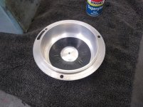
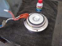
I found a good place to fit the toroidal transformer. Turned a housing for it and cut a hole in the rear cover. Shrunk the ring onto the housing with 10 thou interference. All fits in just nice.

HLV transofrmer housing 1.jpg

HLV transofrmer housing 2.jpg

HLV transofrmer housing 3.jpg

HLV transofrmer housing 5.jpg

HLV transofrmer housing 6.jpg
 
5 pic limit...

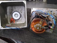
Rear view of housing and wiring ready to go. I can now strip it all out and get the bits painted, then it;'s ready to go.

HLV transofrmer housing 7.jpg

HLV travel motor wiring 1.jpg

HLV travel motor wiring 2.jpg


Back
Top