Floodworks
Plastic
- Joined
- Sep 10, 2020
Hi Everyone,
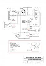
My carriage feed motor is not working. When I first switched the machine on after buying it in August, the motor ran for about 3 seconds then stopped (I had it sitting on the drip tray, disconnected from the carriage). First I found The 2amp fuse conecting two black wires that run to the feed control box was blown on the main board. I also found there's continuity between Earth and the blue and brown wires going to the diode assembly which I assume is some sort of rectifier. I traced this short back to the transformer and there seems to be a short between several of the wires coming out of the transformer and EARTH. There is a small "shadow" of soot surrounding the transformer where it is mounted onto the backing plate.
Anyone have any ideas what might be wrong? Electronics is not my strongest subject but I'm learning.
Many Thanks in advance
Alex