What's new
What's new

Just got my bridgeport...how to wire it???

arik434

Plastic
Joined
Nov 16, 2008
Location
Buffalo, NY
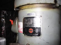
Been searching for a while and finally found my bridgeport. It is a series 1, 2 HP variable speed with x axis power feed and DRO.

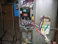
I found it at a local shop where it was still running--which was nice. I picked it up a couple days later and they had already unhooked it. There are 6 wires coming out of the cord and I'm wondering if someone can help me to hook this up. The wire colors are:

Black, purple, yellow, red, white and green.

For now, I plan to run the mill on a static phase converter. At some point I will probably swtich to a rotary style, but for now I will try to make due with what I have. The static phase converter is currently powering my 10" heavy south bend lathe. The lathe seems to work great with this converter.

Thanks in advance to someone who can help point me in the right direction.
 
Green is usually ground. The other five wires are 220 V three phase to feed the motor and 110 V single phase for the DRO and power feed and light if it has one. Find the two wires that feed the 110 V stuff, then the other three wires are for the motor. But make sure the previous owner was not using 440 V for the motor.

It gets a little more complicated if there is a magnetic starter. Then you need to pay attention to which wires from the phase converter go to which inputs in the starter.

Larry
 
Best to Start at Motor Connections and work your way back .

Colors might not be hooked up properly at that end, or Switch, or Panel, etc

Should be a Wiring Schematic Under Switch Cover or on Machine somewhere.

A web Search will find a Machine Manual/Schematic. Is it a Bare Machine with only a Spindle Motor? or do you have 3 Phase Pumps etc? Makes a Difference on which way to go with Convertors. There were several different Motors used, so the Motor plate info is needed for more wiring help.

Static Phase Converters Give you Less Power (~2/3) than a Rotary or VFD.

They also need to be the proper size, and if you have a 2 HP motor on that Lathe, You have too Much Motor on it...

So if you want a Reasonably quick set up, A VFD might be what you need.

Variable Speed Drive and a Variable Speed Head.... :)
 
thanks for the response.

The DRO and light both have their own 110V plugs, so I dont think that any of the wires belong to them. I guess I should start by looking closer at the motor and seeing what wires come from it. I'll take some pics and post here.

Thanks for any other suggestions.
 
Colors might not be hooked up properly at that end, or Switch, or Panel, etc

Should be a Wiring Schematic Under Switch Cover or on Machine somewhere.

A web Search will find a Machine Manual/Schematic. Is it a Bare Machine with only a Spindle Motor? or do you have 3 Phase Pumps etc? Makes a Difference on which way to go with Convertors. There were several different Motors used, so the Motor plate info is needed for more wiring help.

Static Phase Converters Give you Less Power (~2/3) than a Rotary or VFD.

They also need to be the proper size, and if you have a 2 HP motor on that Lathe, You have too Much Motor on it...

So if you want a Reasonably quick set up, A VFD might be what you need.

Variable Speed Drive and a Variable Speed Head.... :)

THanks for the input. Honestly I'm not sure what the motor size is on my lathe. The static phase converter is good for .75-1.5 HP. I thought it said up to 2HP. I guess I'll need to get something different sooner than later for my mill then.

Ok, here are a couple pics from the garage. There are some panels on the back of the mill where all the wiring seems to lead to, so I was poking around in there. The green is definitely the ground. The white and yellow wires were for some 110V outlets on the backside of the mill. Now I am just left with three wires...purple, black and red. Now these three wires are going into this switch/transformer--labeled L1 L2 and L3. The underside of this switch thing has 3 black wires labeled 1, 2, and 3. These are plugged into locations T1, T2 and T3. These 3 black wires run back up to the high/low speed switch.

Ok, this is starting to make more sense....what exactly is this switch thing on the back of my mill? I am wondering if this thing might actually be wired for 480 and not 220/240. It is made by allen bradley and I do see one yellow sticker in there that says "undervoltage proctection 480V"

If this is the case and it was running on 480 at its previous home, can I take the three black wires (1,2,3) that come from the center terminals on the high/low speed switch and use them as the 3 legs on my plug?

I need to go back out to the garage and get the motor nameplate info..I forgot to write it down.

oh, I am running the spindle motor and there seems to be some sort of lube pump/housing on the side of the mill that has 2 red wires that lead back up to the high/low speed switch. Not sure what exactly this is or how it works yet either....


Thanks for any help guys!

Arik
 

Attachments

  • Picture 182.jpg
    Picture 182.jpg
    95.6 KB · Views: 11,102
  • Picture 185b.JPG
    Picture 185b.JPG
    84.5 KB · Views: 14,238
Why buy a rotary

A rotary phase converter simulates true 3 phase....the only difference really is if you plan to speed up or slow down your spindle motor using the vfd - your feed motors and coolant pump will slow down too....this is not the way to go. The vfd should just be used as a static phase converter.....and should not be set up and down - this could harm your machines electronics for the feed motors. the vfd can be used in conjunction with your milling machines belt or gear speed selection, thus not using its frequency setting to change speed.

Much of a muchness really VFD or RPC - RPC is usually cheaper to build...and easier to fix if something goes wrong. There are no heavy electronics involved in an RPC....if your VFD cooks - it usually means buying a new one.

Hope this was of some help :)

Good luck!!!!!

John
 
The motor looks like it is wired for 480 v right now. The box on the back is a manual motor starter with termal overloads (heaters) Allen Bradley W44 might be enough to run the motor on 240 v, I dont have that chart handy. Looks like they had 480 v supply to the machine, powered the motor with the red, black, and purple. The little transformer next to the starter would have dropped the voltage for an outlet for the lights and maybe a table feed. To know what the yellow and white wires were for, you need to look at what the other ends are connected to. If you run off a rotary pahse converter, you can still use the starter but just plug the lights into a 120 v outlet close by.
 
The motor looks like it is wired for 480 v right now. The box on the back is a manual motor starter with termal overloads (heaters) Allen Bradley W44 might be enough to run the motor on 240 v, I dont have that chart handy. Looks like they had 480 v supply to the machine, powered the motor with the red, black, and purple. The little transformer next to the starter would have dropped the voltage for an outlet for the lights and maybe a table feed. To know what the yellow and white wires were for, you need to look at what the other ends are connected to. If you run off a rotary pahse converter, you can still use the starter but just plug the lights into a 120 v outlet close by.

Thanks for the response. It looks like the transformer next to the starter dropped the voltage for some kind of a lube sustem that is on there.

The white and yellow wires were definitely connected to some aux. 110V outlets...I'm guessing that this is where the DRO, light and powerfeed were plugged into.

I guess I am just wondering what would need to be done to convert this system to 220V? Maybe nothing? Do I really need that manual starter or can I just bypass it? What exaclty is its purpose?

Thanks guys for the comments!!
 
The manual starter is also the motor overload protection and a main switch to shut off the power to the drum switch for safety.

One advantage of a VFD is that it provides the on-off, fwd-rev and motor overload functions. In other words, you can eliminate the manual starter and the drum switch if you want to. If you want to keep the drum switch, you can wire it to the control terminals on the VFD. You should still provide a way to disconnect power from the VFD, like a cord and wall plug for your 220 V single phase power to the VFD.

You need to read your motor nameplate to see if it will run on 220 V and how to connect the motor internal wires for 220 V. That is especially important if the motor is a dual voltage motor. You need to establish what power the light, DRO and coolant run on. They may all be 110 V and can be run off a normal shop outlet, completely independent of the main motor wiring. You probably don't need to keep the transformer.

Larry

I took some pics of the serial numbers and nameplates, but I am having camera troubles at the moment. Will post the pics after....but it appears that the motor should run fine on 220v. It does have a little drawing that shows the wires 1,2,3 going to "line" for the high speed. I guess I need to get a RPC or VFD and see if it will start.

I guess I wasnt clear in my earlier post. The dro, power feed and light all have standard 110V plugs on the ends. I think they were just plugged into the outlets on the back of the mill that were hard wired with the white and yellow wires. THe only other thing that I am not sure about now is the lube system on the side and how it actually operates? Any advice?

Thanks,
Arik
 

Attachments

  • Picture 192b.JPG
    Picture 192b.JPG
    58.2 KB · Views: 1,423
  • Picture 193b.JPG
    Picture 193b.JPG
    79.3 KB · Views: 1,261
The lube system should have a voltage plate on it too. most likely a 120 v motor in it. I have a similar one that can be wired for 240 or 120 v. the lube system could be set to run whenever the starter is turned on, or maybe only when the spindle is running, again, need to just follow the wires to where they go and make some logical inferences.
The motor plate shows the wire hook up for 240 volt (low voltage) just find the wire numbers and make sure they match up like the motor plate shows.
You could try starting it with the static converter. low vollt hook up wire line 1 to 1 and 4, line 2 to 2 and 5, line 3 to 3 and 6. then hook 7,8.9 together.
 
I traced the wires back to the start switch. Would this kind of pump run continuously? Or just supply some lube and shut off? Just curious....
 
That lube pump has a small clock motor in it that runs through gears and a worm drive to lift a plunger with a cam. When the cam reaches top, it drops the follower and spring pressure pushes the pump piston down. My pump like this cycles once every 15 minutes when power is on. The fittings on the lube lines meter the oil so you arent pumping any big quantities.
 
Some questions about VFD vs. RPC

I don't want to hijack your thread arik434, but I have a couple of questions that are related to this subject.

I just bought a 1963 J head and I have been stumbling through a bunch of posts about static phase converters vs VFD units vs rotary phase converters and I want to clarify a few things.

If I understand things correctly:

With a VFD I would need to wire it directly to the motor and I would eliminate the starter and drum switch.

Static phase converters seem like they would be sensitive to lots of starting and stopping and they reduce the HP by about 1 third.

The rotary phase converters seem like they offer the longest service life, they require no changes to the machine wiring and the machine can run at full HP. It is my understanding that I could basically hook the mill power cord to the RPC and drive on.

Also, if I plan to buy a 3 HP lathe in the future, I can get a 5 HP RPC now and run my 1 HP milling machine on it with no ill effects.

I am leaning toward the RPC converter, but I am electrically challenged so I wanted to make sure that I understand everything correctly and I am not missing anything.

Are there drawbacks to the RPC for home shop use?

Thanks
 
RPC Drawbacks

Biggest is Space.... Take up Room, Usually do not hang on a Wall Nicely like a Static or VFD.

They cost quite a bit to Buy, but can be cheap to make if you have free Idler Motors around.... They Require Tinkering and Tuning if building, and Have High Voltage running around for you to Test and Tweak for your uses ( if Homebrew from Surpus parts). Great if you like to tinker with High Voltage/ Current ....

VFDs cost in your case less than 300.00, offer Variable Speed, Adjustable Accell and Decell/Braking, that RPC's don't. Only 2 hot 220 wires running into VFD and 3 hot 220 3 Phase wires running directly from VFD to Motor (Grounds needed of course)

Rest of VFD wiring is Low Voltage ~10 to 24 Volts and almost no Current. A goof up will produce an error on Display or not work right No big $$$ Smoke Cloud,

They cost not much more than a Static Converter and offer Motor Overload Protection Built in, that Statics and RPC's do not.

VFD's do not easily operate more than one Motor at a time, so If Pumps, DROs or other Equip need 3 phase, a RPC is simpler...

So What works for you and your Machine differs. If you want a VFD and dump 3 phase Pumps/etc, you can do it that way, or go RPC or Static,
Depends...

Having a Static and wanting To Power Reverse for me, meant time to get a VFD. Static just humms and Spindle keeps spinning same direction...

RPC would give me Power Reverse, but no Variable Speed/Brake Cycle, (and My Shop is Small)
 
Ok, I was finally able to get a hold of the previous owner and the mill was infact originally wired for 440V power. Does anything different need to be done differently to use 220V power? I realize that the motor nameplate has both voltages listed, but I just dont know if any of the wiring would need to change.
 
Been searching for a while and finally found my bridgeport.

For now, I plan to run the mill on a static phase converter.

Don't do it.

Friends don't let friends use a static converter.

Don't use a static on any motor that you care about. There have been far too many cases of cooked motors due to the use of static converters.

There are too many axioms that are apropos in this situation to recant them all.
 
With a VFD I would need to wire it directly to the motor and I would eliminate the starter and drum switch.

It is best to view the VFD as a contactor, overload, (magnetic starter), phase converter and speed controller all wrapped up in one.

You can use the existing controls with a VFD, you just need to wire them up to the VFD instead of your contactor(s) (starter).

You could use the existing contactor with the VFD if it 230 volt capable, but not sure why you would. In this case you rewire the starter contactors to control the VFD.

A Teco 2hp VFD is about $145.00 www.factorymation.com is one supplier.
 
Ok, I was finally able to get a hold of the previous owner and the mill was infact originally wired for 440V power. Does anything different need to be done differently to use 220V power? I realize that the motor nameplate has both voltages listed, but I just dont know if any of the wiring would need to change.

Someone told me that there should be a diagram on the motor somewhere stating that the 220 wiring will be different than the 440? Is this true? I took a quick look at the motor and the top motor cover, but do not see any diagrams...?


Back
Top