What's new
What's new

DRO install without the cheesy hardware

ZAGNUT

Hot Rolled
Joined
Nov 30, 2008
Location
Israel
all those "universal" brackets that come with the less expensive DRO kits just end up looking like a mess to me, there's got to be a better way. seeing that anyone who sets out to install a DRO on a mill should already have the mill up and running why not make some custom brackets that look good and won't get knocked out of alignment with the slightest bump?

i'm going to post my progress with the sino kit and hopefully others can add in their custom setups as well.


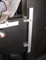
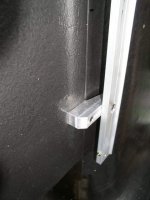
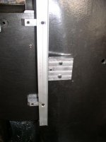
i started out with the Z axis on the knee. instead of the wraparound kludge of 10 angle brackets and 45 screws i decided that the scale should move with the knee and the head should be fixed to the column. but i still wanted the scale to be back aways over the column so it wouldn't interfere with the Y axis or the lube zerk. the pics of the two standoffs are self explanatory. the 20mm plate that mounts the reader head to the column is held in place with two screws and has three set screws for leveling. the big set screw right next to the scale sits in a shallow dimple drilled in the column to keep the whole mess from wanting to slide down towards the scale when tightened up. in retrospect 4 leveling screws would have probably been easier to adjust. the adjustment of this plate can pretty much be eyeballed because the reader head itself has 4 adjusting screws as well.

wait for the edit so the pics can be attached...:rolleyes5:


dave
 

Attachments

  • z.JPG
    z.JPG
    24.3 KB · Views: 1,571
  • zclose.JPG
    zclose.JPG
    31.6 KB · Views: 1,418
  • zhead.jpg
    zhead.jpg
    37.2 KB · Views: 1,316
  • zshield.jpg
    zshield.jpg
    30.8 KB · Views: 1,898
Last edited:
I see you are mounting it reverse of what people usually do ,including me, with the scale moving instead of the reader head.
I have to fit another DRO on a mill I might copy this idea.(if it's not copyrighted, LOL)
Good job and great work will watch with interest.
Davo
 
Dave,

Looks like a nice clean install. I'm in the process of installing an Acu-rite scale on the knee of my Induma. I'm having terrible luck drilling into the cast iron. Maybe I'm using the wrong kind of bits(?) What kind of procedure/bits did you use to drill/tap the holes?

Thanks

Mike
 
after center punching i'm just going in with bog standard twist drills, either guhring or ETM brand. lots of pressure and playing with the trigger until i find the sweet spot, probably something like 1000rpm or lower. then i go in with regular spiral tipped machine taps by hand. if i can keep the handle turning in one fluid motion i don't back off to break the chips until i'm all the way through.

only hard ones were the two holes in the column that are at an angle because of the shape down there. no matter how careful i was they still came out off the mark. so i had to enlarge the holes in the plate a hair and use washers under the screws. not a problem since the screws are only there to apply pressure, the set screws against the column are what locates the plate and keeps it from moving around.
 
onto the Y axis which is pretty standard in comparison to the Z. in my first post pics the mounting bar can be seen attached to the side of the knee. it's held on with two screws and at each point there is an alignment pad with two set screws between the bar and the knee. what's nice is that the gap left will allow all the way oil to run down the side of the knee and not pool up on top of the scale shield.

the bracket for the reader head is made out of 6mm alum plate and uses all four of the holes in the saddle for mounting. to get the bolt and cutout patterns i just held a piece of thin cardboard up to the side of the saddle and went over it lightly with a plastic hammer.
 

Attachments

  • yplate.jpg
    yplate.jpg
    30.8 KB · Views: 741
Zagnut... Can you spitball the dimensions on those 2 brackets for the Z axis you made for me please? Also, what size hardware did you use to attach those two to the knee? This has got to be the best setup for the Z I've seen so far.


Thanks!
Jason

OMG, I just noticed this thread is over a DECADE old. The mill has probably been long sold and he now has some fancy 5axis cnc stuff.
Sorry gang.
 
Since I am new to CNC, this thread does strike a question for me. If the OP was putting a DRO on the knee, would that be as opposed to having the DRO on the quill / or is there a way to have a DRO on both and have software compute the sum of the 2 positions?
 
Since I am new to CNC, this thread does strike a question for me. If the OP was putting a DRO on the knee, would that be as opposed to having the DRO on the quill / or is there a way to have a DRO on both and have software compute the sum of the 2 positions?

Yes, it's possible although I don't recall if the summation is done in the DRO or if that was a separate module. A search through the forums should yield results.

Here's one link with some discussion of DRO's capable of that. 3 or 4 axis DRO on 9x49 mill?
 
What I've seen more commonly is to use a 4 axis display that has both Z axis read-outs labeled separately (Z and Z-quill for example). They don't get combined because they don't get simultaneously used. You're either positioning with the knee and then pecking with the quill, or locking the knee in place with sufficient clearance and doing all movement with the quill or visa-versa. I think combining them would make it confusing. If Z moves accidentally... where and how did it move?


Back
Top