The 2J I got had the feed screws entirely disassembled when I received it, so I have no idea what went where when it was taken apart. I am hoping some of this stuff looks familiar to other people here that can give me some direction on the best way to reassemble the X-axis feed screw so it works properly. It was made in 1970, so I've already run into current parts not matching up. There is supposed to be a power drive on the X.
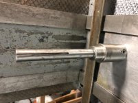
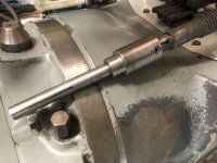
The feed screw has had one end modified, I believe it was to fit the power drive. There is an extension that gets pinned onto one end of the feed screw.
Here are some pictures before cleaning and reassembly, and then after installation:


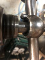
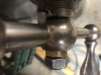
First thing. On the left side, the handle is too large for the shaft. It appears there is a bushing / sleeve that is approximately the correct ID , OD, and length, but the sleeve would allow the handle to move in/out and the sleeve appears to not old up well to the nut being tightened to it.


Is there a more correct way for this attachment? Do I have the wrong components somewhere?
The feed screw has had one end modified, I believe it was to fit the power drive. There is an extension that gets pinned onto one end of the feed screw.
Here are some pictures before cleaning and reassembly, and then after installation:


First thing. On the left side, the handle is too large for the shaft. It appears there is a bushing / sleeve that is approximately the correct ID , OD, and length, but the sleeve would allow the handle to move in/out and the sleeve appears to not old up well to the nut being tightened to it.


Is there a more correct way for this attachment? Do I have the wrong components somewhere?


