Any and all ideas would be greatly appreciated! Purchashed a used older Bridgeport J Head. When I attempted to adjust the head angle left to right as you face the machine, the head of the adjusting worm shaft just spun with no results. Removed the J head from the machine. I could see sveral things: The Quill Housing Adjusting Gear (mounted on the main body of the machine)had it's two mounting bolts sheard off, and the front third of the teeth on the gear were all ground down. Second I could see the worm gear on the J head was all chewed uo and spun freely without the Adjusting Worm Shaft turning. The shaft of the Adjusting Worm Shaft had broken somewhere just past where the set screw holds the shaft from moving inor out. Sooo, the Worm gear has a portion of the shaft from the adjusting Worm shaft all the way through it and part way back into the hole for the entire Adjusting worm shat. In addition, the key in the Adjusting Worm Shaft got all buggered up and has jammed up somehow in the hole making the removal of the Adjusting Worm Shaft the major problem. I was told by one of technitions for Bridgeport to just try prying the Adj Worm Shaft out somehow. The problem is getting under the lip of the bolt shaped head of the Adj Worm Shaft to pry on. I have been able to pry it out about a quarter of an inch, but I can not get a good enough grip to move the shaft out any further. Any ideas on what to do now? I thought about welding a ring to the bolt type head of the Adj worm Shaft to put a bar through to use as leverage point to pry out the shaft. What are your thoughts and ideas? Also I'll have to somehow cut with a small saw type tool to cut the stub of the shaft stuck on the worm gear itself to free the worm to drop straigt down out of it's position. Any ideas here also? Thanks very much for any and all help! If you need more explanation just ask me how to better explain the situation.
How to install the app on iOS
Follow along with the video below to see how to install our site as a web app on your home screen.
Note: This feature may not be available in some browsers.
Largest Manufacturing Technology Community on the Web
Stay Connected:
You are using an out of date browser. It may not display this or other websites correctly.
You should upgrade or use an alternative browser.
You should upgrade or use an alternative browser.
Need Ideas How To Remove Damaged Adj Worm Shaft
- Thread starter Smokin AK
- Start date
- Replies 13
- Views 10,810
I removed one just like you describe by drilling and tapping the hex head. Used a slide hammer to bump it out while turning it back and forth with a 3/4 wrench. It sort of knurled the bore, just ream or hone it to fit the new pinion. The driven gear can be rotated 180* to put the damaged teeth at the bottom. You can buy the pinion shaft and gear from High Quality and several others.
N
NewMiller
Guest
Wish I had read this post earlier, as I've gone through the same thing with my 1963 J-head. You've probably dealt with it by now but my experience might have helped.
The damage to my machine was not quite as bad as yours. My fixed gear only had one tooth damaged so I welded that tooth up and ground it back to shape. The big problem was the worm gear and shaft.
My shaft had sheared at the point where it enters the worm gear, protruding into the worm gear enough to capture it in the housing recess. I used a die grinder with an abrasive cut-off wheel to cut the worm gear in two in the center (only nicked the housing in a couple of places) and was then able to pry the two halves out. Then things got difficult. The remainder of the shaft would turn but could only be worked outward a fraction of an inch. I spent several hours working on this before I finally took a 12" length of 3/4" threaded rod and welded it to the head of the shaft. I slipped a shorter length of pipe over the rod, followed by a heavy washer and nut. With the pipe resting against the housing (had to weld a little leg on the side of the pipe to help keep it centered) I tightened the nut and jacked the shaft out of the housing - not easily!
I expected the bore to be damaged from all this but it seemed to be in pretty good shape. So now it's just a matter of buying a replacement shaft and worm and dropping them in the housing, right? Well, my replacement shaft was about a half inch too long. I'm guessing that the reason for all these worm gear problems was that the early mills had the worm supported on one end only, allowing the shaft to flex at that point under extreme load, leading to problems. Anyway, it seems that at some point Bridgeport extended the bore about a half inch into the other side of the worm gear recess to support the shaft on both sides of the worm. I finally turned a bushing (drill guide) to fit in the large part of the bore, with the center of the guide drilled for the shaft extension. Then I slipped this guide into the bore and used a hand drill to extend the bore a half inch into the far side of the worm gear recess. Now the worm and shaft fit and everything seems to be fixed. I'm still cleaning and painting the rest of the machine so I haven't yet been able to reinstall the head to try it out.
Hope this helps someone.
[This message has been edited by NewMiller (edited 04-19-2003).]
To NewMiller: You post has helped some one - me! The parts I ordered were/are on backorder, I'll call on Monday to make sure the person who took my order knows that I too have the older style like you do. My pin does not go through the worm gear into a recess on the opposite side, the pin stops within or just at the end of the worm gear. The person I spoke to did know I had an older machine, but he only thought the diiference in the adjusting worm shaft may be that it had a "slightly" larger diameter, and that I might neet to use a bore hone to slightly enlare the bore diameter for the worm adjusting shaft to fit into. He never mentioned that it might be longer and need to go through the worm gear and into the far side. Also, my fixed gear must have broken both holding bolts long ago, every tooth for the full 360* was damaged, I had to order a new one. I too have not had a chance to fire mine up. I can't wait! I hope this is the only "surprise" I find. Thanks again for the help.
Smoking AK
[This message has been edited by Smokin AK (edited 05-07-2003).]
Smoking AK
[This message has been edited by Smokin AK (edited 05-07-2003).]
One more question while we are at it here. Where or how are you supporting the head so that when you go to put it back on, that it is lined up correctly? I had just put a protected chain under the top cover between the top two pulley sets. I used a shop crane to lift up on the chain as I pulled the head off of the main body of the mill. Needless to say it canted backwards badly once the head dis-engaged from the rim on the main body. I had a hell of a time getting the head the rest of the way off. I had to cut one of the "T" bolts to releive the pressure on the other "T" bolts to get the head all the way off. So, now how do I get it back on straight and aligned properly? Are there certain holes that you put eyeletes through? Is there a special way to cradle the head? It is pretty much just me and the wife available to put the head back on, and due to back problems, I cannot lift or hold heavy weights of any kind. Thanks again for all the help.
Smokin AK
Smokin AK
N
NewMiller
Guest
I lifted mine off with a come-along from a temporary arm I rigged overhead, but I was luckier than you were. Some time ago someone posted another method to remove and install a head. He machined a piece of 3/4" CRS so that it could be bolted in a T-slot, then chucked this in a 3/4 collet in the spindle. This holds the head vertical while you use the table to position it for removal or installation.
I think I'll try a variation of this when I reinstall my head. I took a 4"x4" square of 1/4" steel and welded a 5 inch long piece of 3/4" CRS vertically in the center of it. Then I drilled a couple of holes in the corners to bolt the plate to the table. *IF* (big IF) I can get the head on this, positioning to bolt the head in place should be easy. I suggest removing the motor untill the head is back in place.
Setting the head upside-down might be a lot easier than trying to get the collet over the 3/4 post, though.
I have a hydraulic lift table that I bought from Harbor Freight that saves a lot of back strain sometimes. If I hadn't had that I doubt if I could have gotten the table off my mill.
does eny one have a jpg of the new gear for the j head .that matchs the worm gear need to see what a new gear looks like .got the worm replaced . now im thinking maybe my big gear has been fliped over before ,jim whats the cost and the cheepest place to buy a new one .
I don't know if this is the cheapest (least expensive) option, but I purchased mine through Bridgeport/Hardinge or is it just Hardinge now? Their phone number is 800-243-4292. Anyway, in my 1961 manual, it describes the part in question as: part number J144 "Gear - Quill Housing Adjustment Gear." The gear is not available by itself through Hardinge, it comes in a kit form with the two hex head bolts and the pin. The kit part number is 12193500, cost is $179.00 plus shipping. NOTE: This is for my model year mill, I do not know what years this kit is compatable to. I do not know how to post a picture here. If you send me your E-mail address, I can send you a copy of the picture of the gear. I hope this helps in some way.
Smokin AK
Smokin AK
N
NewMiller
Guest
Jim, you can get the gear (and anything else for a Bridgeport mill) from McDowell Machinery & Supply in Dallas (214-353-0410). I don't know if they ship parts but I'll bet they do.
Calibre41
Plastic
- Joined
- Oct 24, 2013
- Location
- United Kingdom
Good thread, just what I needed however I took a slightly different approach - only took about 20 minutes, no special tools, drills or taps required just an M6 bolt or similar and an M6 hex connecting nut....
My shaft had sheared almost at the top of the worm gear, so I couldn't pull the worm gear out, I used a ring ended 3/4 on the bolt head and using a twisting motion while pulling up diagonal to the bolt center line (so the ring end didn't slip off) I managed to get it off enough to pry out the worm, I also chiselled away at the bolt so likely a combination.
I then used an M6 bolt threaded into a joining nut (from a generic 52 piece clamp kit) inside the head, and simply unscrewed one from the other, pushing the adjusting worm shaft out, when I ran out of threads, I just stacked a few M12 nuts up inside and repeated - just be careful what you use to stack inside I think M12 nuts are ideal - they can't get jammed, they can't twist, they sit flat and have no sharp edges.

Last edited:
I thought I'd add to this thread, as the information contained here has been very helpful as I address the same "broken bolt" problem. I used the same approach as Calibre41, and wanted to share some photos, as I had a slightly different approach.
Separating the head from the Ram was straight forward, as I used the Mill Head Removal Post from H&W ($50 well spent); it allowed me to use the machine itself to remove the head, and to keep it aligned. I bolted the Removal Post to the bed, loosened the 4 bolts, and moved the table along it's "Y" axis to separate the head from the ram. I then rotated the head 180 degrees for easier access to the bolt.
Bonus Tip - I had to retract the ram to get the 4 bolts from the head to clear, but my ram was stuck, as I'm sure it hadn't been moved in years. I had been soaking it in PB Blaster for the 2 weeks I've owned this machine, while looking up ideas on how to get it "un-stuck." When I mounted the head to the Removal Post, it occurred to me to "gently tug" on the unlocked ram while I had it (and the head) attached to the table, before I removed the head...and it worked! I was moving very slowly, as I wasn't sure if I would cause any damage, and made a witness mark with a Sharpie to see if I had any movement when I retracted the table on the "Y" axis. I'm pretty sure I was using the Removal Post in a way in which it was not intended, but it worked for me in my situation. Results may vary.
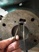
I used the coupling nuts to push the broken bolt out, using 1/4-20-18 bolts of 3/4" and 1" length, respectively, to push the coupling nuts against the broken nut. I started with the 3/4" length, then as space was made available, I switched to the 1" bolt and stacked the coupling nuts as needed (I did cut down one of the coupling nuts, so that they would fit). Once the bolt was in a position where I could use a brass drift, I gently tapped it out of the hole. One note: I used two wrenches, one to hold the bolt still, and one to leverage the coupling nut against the broken nut to push it out: I found that by capturing the box end of the wrench around the bolt head, it was much easier to maintain contact with the bolt head (using the open end was not as elegant, as it kept slipping out)
The head adjustment bolt had snapped cleanly at the base of the worm, so I simply used an arbor press to remove the broken shaft from the worm, and I plan on reusing the worm (as it's in good shape, and they are not cheap). I also reinstalled the gear inside the ram at 180 degrees from it's original position, as the teeth were chewed up quite a bit on the top. I'm hoping this works, as the replacement part is $190.
Parts are on order, and I hope to have this back in service by the weekend. I just wanted to share this approach, and photo's, as it went very smoothly.
Separating the head from the Ram was straight forward, as I used the Mill Head Removal Post from H&W ($50 well spent); it allowed me to use the machine itself to remove the head, and to keep it aligned. I bolted the Removal Post to the bed, loosened the 4 bolts, and moved the table along it's "Y" axis to separate the head from the ram. I then rotated the head 180 degrees for easier access to the bolt.
Bonus Tip - I had to retract the ram to get the 4 bolts from the head to clear, but my ram was stuck, as I'm sure it hadn't been moved in years. I had been soaking it in PB Blaster for the 2 weeks I've owned this machine, while looking up ideas on how to get it "un-stuck." When I mounted the head to the Removal Post, it occurred to me to "gently tug" on the unlocked ram while I had it (and the head) attached to the table, before I removed the head...and it worked! I was moving very slowly, as I wasn't sure if I would cause any damage, and made a witness mark with a Sharpie to see if I had any movement when I retracted the table on the "Y" axis. I'm pretty sure I was using the Removal Post in a way in which it was not intended, but it worked for me in my situation. Results may vary.
I used the coupling nuts to push the broken bolt out, using 1/4-20-18 bolts of 3/4" and 1" length, respectively, to push the coupling nuts against the broken nut. I started with the 3/4" length, then as space was made available, I switched to the 1" bolt and stacked the coupling nuts as needed (I did cut down one of the coupling nuts, so that they would fit). Once the bolt was in a position where I could use a brass drift, I gently tapped it out of the hole. One note: I used two wrenches, one to hold the bolt still, and one to leverage the coupling nut against the broken nut to push it out: I found that by capturing the box end of the wrench around the bolt head, it was much easier to maintain contact with the bolt head (using the open end was not as elegant, as it kept slipping out)
The head adjustment bolt had snapped cleanly at the base of the worm, so I simply used an arbor press to remove the broken shaft from the worm, and I plan on reusing the worm (as it's in good shape, and they are not cheap). I also reinstalled the gear inside the ram at 180 degrees from it's original position, as the teeth were chewed up quite a bit on the top. I'm hoping this works, as the replacement part is $190.
Parts are on order, and I hope to have this back in service by the weekend. I just wanted to share this approach, and photo's, as it went very smoothly.
Attachments


Similar threads
- Replies
- 7
- Views
- 677
- Replies
- 0
- Views
- 322