Halcohead
Stainless
- Joined
- Apr 10, 2005
- Location
- Bay Area, Ca
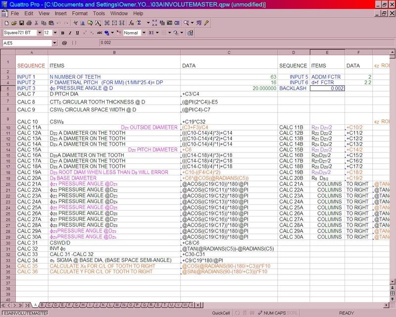
I'm modeling a clock in Solidworks 2005. I don't need a stinkin' CAD program to design the clock, but talking to the waterjet at work might not work as well as feeding it DXF files...
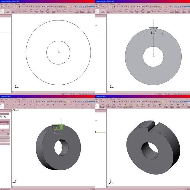
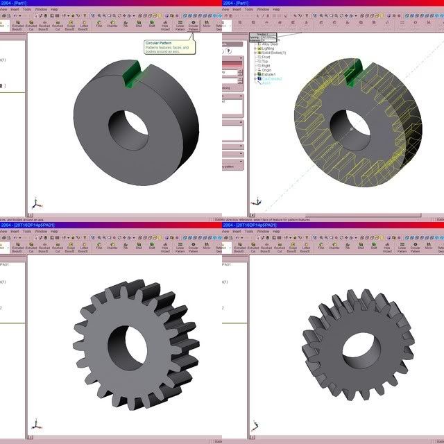
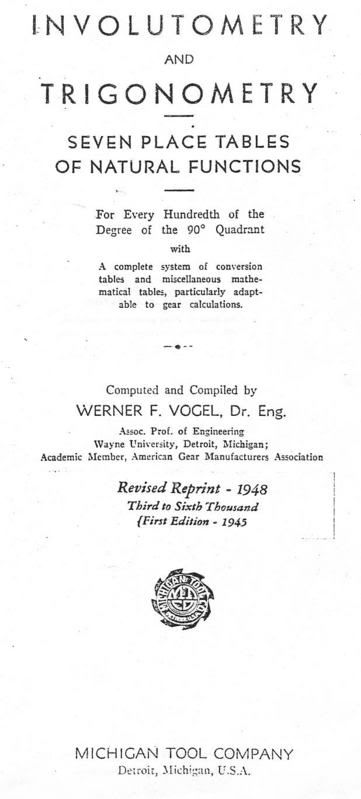
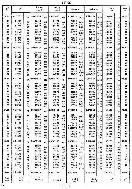
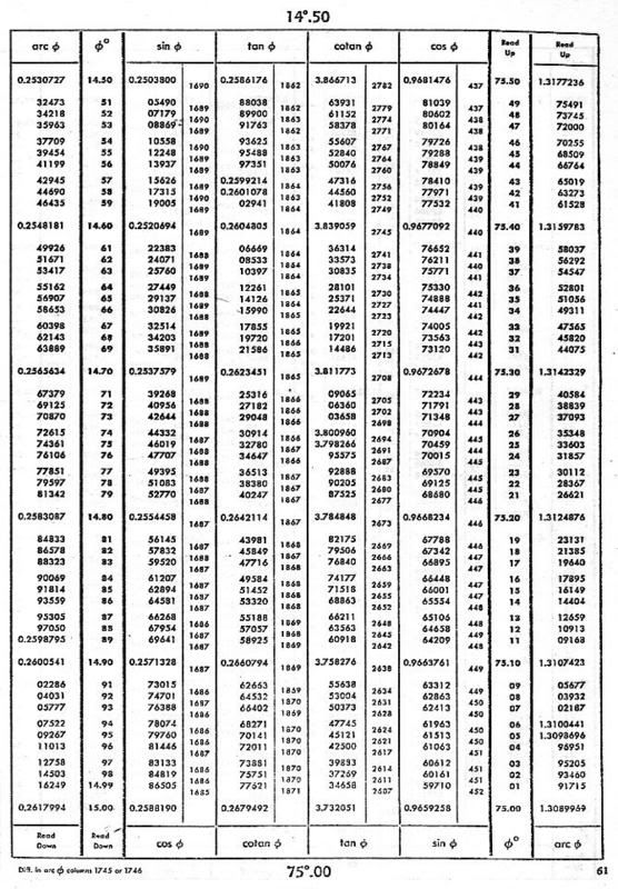
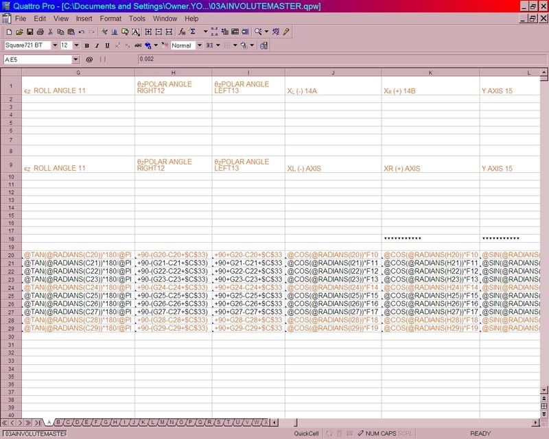
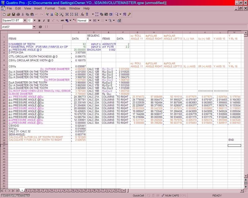
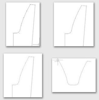
So how do you guys draw simple involute profile gears in Solidworks? I've already read Machinery's Handbook, searched online, and searched this forum. At one point I got pissed, sat down with my calculator, and manually drew an involute curve using a bunch of "for construction" centerlines and the spline tool to interpolate the curve betweent he laid out points. That worked, but it wasn't exactly an ANSI standard tooth profile, and I don't have the patience to do that for multiple gears.
Is it possible to take a gear someone else made and mess with the equation set to change the parameters? hell, I don't even know how to input equations.