What's new
What's new

Limitation with Inventor CAM.. SolidCAM much better??

Schjell

Aluminum
Joined
Jan 16, 2020
Just met the wall here with Inventor CAM (same as Fusion I suppose).
For wrapped 4th axis (C-axis on lathe) milling there is a limitation that dictates that the tool will always require to point towards center/origo (z-axis) and it will apparently not use Y-axis.
I don't have any hope for this being fixed anytime soon either, so many other things that have been requested for years..

Does anyone here know if SolidCAM is significantly better than Inventor CAM (or Fusion, HSM, whatever you want to call it - same kernel) in terms of functionality?

Not really interested in a standalone CAM program - love the integration of CAM in the Inventor models.
 
They have recently added Collision avoidance to 4th rotary in Fusion 360 That may help you.

All of the new development will be in Fusion. I believe your Inventor files will import nicely now. My Solidworks HSM don't come in with the toolpaths or help sketches.
 
Wrapped surfaces are by definition continuously perpendicular to the tangency of the cylindrical surface. What you are describing is not a wrapped toolpath, it is a 4ax toolpath.

AFAIK, Inventorcam has a reasonable amount of 4/5ax strategies available, so I would suggest that you're just looking in the wrong place for the functionality you need. Without seeing the geometry you're trying to cut I can only guess, but I expect that a swarf toolpath is what you should be looking at.
 
They have recently added Collision avoidance to 4th rotary in Fusion 360 That may help you.

All of the new development will be in Fusion. I believe your Inventor files will import nicely now. My Solidworks HSM don't come in with the toolpaths or help sketches.

Apologies for late answer. I just checked out that new feature you mentioned, it's moving in the right direction. Who knows - maybe one day I can see my tailstock in the simulation as well:-)
That being said, we have Fusion and we used it earlier, especially for 3 axis router work. But we are a business which is growing steadily and we have about a thousand unique parts that are all used in various assemblies and associated drawings, so for the foreseeable future we will try to keep everything within Inventor in order to avoid a revision hell.
The fact that you can't open files directly from a disk in Fusion is absolutely nuts. I haven't used Fusion much, but I still had four or five occasions when it didn't work - connectivity issues with cloud or some bullshit. To put things in perspective - we got a rush job where we needed to work all day and all night in order to get the job. Those 36 hours of work paid down a full years interest and leasing cost for our Haas ST-30Y. If I were using Fusion there's a good chance we would have been screwed and failed to deliver. I hate clouds and that's not going to change.
So the fact that AD is pushing all development in Fusion and seem to forget the Inventor users is a poor strategy in the long run I think. It's going to push companies like ours towards MasterCAM and Gibbs and they will be left with the smaller shops (though numerous) using Fusion who can tolerate its shortcomings. It's cheap as chips, so I'm not putting Fusion down - it's just not for us - we need reliability. Sorry for this becoming a Monday morning rant - need some more coffee before I brighten up:-)
 
Wrapped surfaces are by definition continuously perpendicular to the tangency of the cylindrical surface. What you are describing is not a wrapped toolpath, it is a 4ax toolpath.

AFAIK, Inventorcam has a reasonable amount of 4/5ax strategies available, so I would suggest that you're just looking in the wrong place for the functionality you need. Without seeing the geometry you're trying to cut I can only guess, but I expect that a swarf toolpath is what you should be looking at.

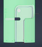
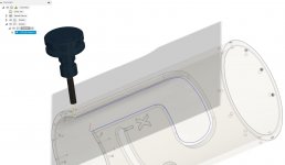
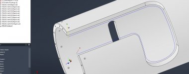
Hi Gregor, I see what you mean - thanks for the input. I added some pictures of what I'm trying to do. As you see the toolpath does not follow the contours. I've tried the swarf strategy before with no luck - I think it's intended for 5th axis milling heads that can roll around all over the place.
Will give swarf another go! Inventor CAM is ok for turning and simple milling, but maintaining some sort of control of the toolpaths for milling is generally a PITA. Helped out a bit when I realized I can make dummy sketches in the model and use these to force the toolpaths where I want them to be.

2D countour 4th axis - 1.JPG2D countour 4th axis - 2.JPG
 
So solidcam sells a product called InventorCAM - and I presume (but do not know) that it's solidcam reworked to run inside autodesk inventor rather than inside solidworks. Maybe you are talking about a different product with a similar name?

In any case, there are two youtube channels that are often very helpful (at least to me) for solidcam...
SolidCAM University - YouTube
SolidCAMProfessor - YouTube

Hi Bryan - Yeah that's the software I was talking about. I was confused - the way they present their software led me to believe this was an official AD product, but I see that it's a 3rd party plugin now. Seeing that you use it - What's your opinion on it? Is it significantly better/more capable than Inventor CAM/Fusion/HSM?

I foresee that within the next two years we are likely to exchange or supplement our Haas revolver lathe with a Mazak Integrex or Doosan SMX which does all that fancy stuff that I see in the marketing videos - balanced OD turning or perhaps milling on the second side ops while it's turning on the first side ops. Not saying we are going to be doing this stuff, but I'd like to settle on a CAM system that will allow for "everything".
 
Hi Gregor, I see what you mean - thanks for the input. I added some pictures of what I'm trying to do. As you see the toolpath does not follow the contours. I've tried the swarf strategy before with no luck - I think it's intended for 5th axis milling heads that can roll around all over the place.
Will give swarf another go! Inventor CAM is ok for turning and simple milling, but maintaining some sort of control of the toolpaths for milling is generally a PITA. Helped out a bit when I realized I can make dummy sketches in the model and use these to force the toolpaths where I want them to be.

View attachment 334501View attachment 334502

I think this might be why my tool paths are not doing what I want them to do, not sure though.

Wrapped 4-axis toolpath does not cut edges of Pockets correctly in Fusion 360 CAM | Inventor CAM | Autodesk Knowledge Network
 
Used swarf - no luck

The swarf strategy made near perfect toolpath at first attempt, but sadly the post for my machine does not support it.
It's annoying considering that it does not require any tilting head movements.
As far as I can see from my model, the walls in the model would allow milling just with C-axis rotation and X & Z movemements. Note that this is a lathe.
Making me grumpy!
swarf2.JPGswarf1.JPG
 
FYI - Worked like a charm when I tested doing this in Fusion. Same as I tried in Inventor - 2D wrapped contour.
Waiting for a call from Gibbscam rep, see they have a good Inventor plugin - fed up with Inventor CAM and can't use Fusion on a daily basis, enough is enough.
Fusion worked.JPG
 
FYI - Worked like a charm when I tested doing this in Fusion. Same as I tried in Inventor - 2D wrapped contour.
Waiting for a call from Gibbscam rep, see they have a good Inventor plugin - fed up with Inventor CAM and can't use Fusion on a daily basis, enough is enough.
View attachment 334508

I think you're jumping the gun. It still hasn't been established that the surfaces you are trying to cut are possible to cut with a wrapped toolpath. Have you done a solid volumetric compare on that Fusion path to see if it is leaving or gouging material?

Are the edges of the profile you are trying to cut intersecting the centreline themselves or are they offset?

The link that you posted above from autodesk does a pretty good job of explaining this.

A four axis simultaneous path where the Y has to be moved to hold the tool parallel to the wall IS a swarf path, not a wrapped one.

I don't understand what you mean by your post doesn't support the swarf path? There is nothing special about it, it will just post a lot of xyzc G1 moves. Do you mean it is trying to post B moves? If that is the case you probably need to constrain one of the rotary axis, there is very likely a setting for that somewhere in your swarf path, which will make it a four axis path instead of a five axis one. I don't know what it might be called in Inventor cam, something like "lean only" or maybe you have to explicitly set the limits of B to 0... Something like that, there will be a way...

Hi Gregor,
Well I've made bunches of different parts that do just the same, so the toolpath that Fusion spit out is likely valid, no doubt about that. My point is that Inventor CAM has been a moody SOB lately. Latest one happened today during a simulation. "Stop on collision" is turned on and no collision is detected when the boring bar plows straight into the stock rather than into the drilled center hole. What's worse is that when I generated the code last Thursday everything was fine. Sometimes I feel like I'm losing my sanity. I sent a video of the latter to my AD reseller - just not acceptable by any standards.

EDIT1: Added a picture, since video upload not possible. Note that "stop on collision" box is ticked as "on". No red flag along the bar at the bottom either. What the hell is happening to my CAM these days.. Scary stuff if I was boring stainless steel and the collision was not so in your face obvious.

undetected crash.jpg

EDIT2: I did a visual comparison in Fusion, as expected it machined as planned. All the milled edges are perpendicular (if that's the right choice of words), their faces, if extended, would pass through the center of the part if that makes sense, so definitively wrapable and machineable without use of Y axis I would have thought. It is as straight forward as it seems.

I am unable to use latest CAM update (build 9.2.1.26417) as AD asked me to uninstall and roll back to an earlier version (Build - 9.0.0.2479) as the latest version could not handle this: "As I understand from the description, when creating a 2D contour wrap toolpath, an error pop up "the wrap radius must be larger than zero for axis substitution". I apologize for the inconvenience caused to you. I am truly sorry to say that this is a known issue in Inventor CAM 2022.1.0."
 
Schjell - solidcam with solidworks is the only CAD and CAM I've ever done serious work with. My attempts to do anything at all in fushion have been... frustrating....

A non-profit, and some student groups, I work with end up using fushion, so I export the files and read them into solidworks.

Fusion is very much evolving, so any particular thing may be better now than when I last tried it. On the other hand it will sometimes refuse to work at all until you update it (very slow) and has the cloud data integrity issues everybody talks about.

But I'm a peculiar person, so don't base your thinking on what I do.

In Addition:

Are you trying to use an XZC only post to control an XZCY lathe? That might explain the post issue.

Yeah, Fusion is definitively getting better day by day. Such a shame that it requires that cloud stuff to work.
Regarding XZC / XZCY I haven't gone into any advanced settings and changed stuff, so my approach to stuff like this is that if it worked last week it should work this week.
Regardless, my troubles are before using the post - it was not making correct toolpaths.
AD support managed to do what I could not do and sent me my IPT file back today. When I tried to make the milling op just now, it worked.
Problem solved, but I have no clue why it did not work earlier, so I am non the wiser.

it works.JPG
 
I'm with Gregor on this. To me, "wrapped" toolpath means keeping the tool-axis intersecting the rotary axis, or normal to the surface you're wrapping about.

If the part's walls intersect the rotary axis, or are normal to the OD, then the toolpath has to perform an Y-offset on any Z-movements to not gouge or leave stock.

Actually that's kinda cool if fusion can do that offset for you. It is really a swarf toolpath, but generated from 2D.

If it works, cool.


But, you have to 'unwrap' it first, right? To figure out the size of the 2D-feature to cut pre-wrapping? Gotta be a better way to do it from the model without drawing extra geometry.

Yes, the part in question fits the "wrapped" description, so that's what I did. Just in 2D contour just select the contours and the diameter you want to wrap around and it's sorted (usually in a minute - this time it took two working days for some buggy reasons I'll never understand.

For the latter with parallel sidewalls I just pick the tool vertical z-direction and go for 2D contour without wrap and the Y-moves are processed automatically.

Long story short - finally made the part in question today only to realize that there's a flaw in the fundamental design, so in the end all this hassle was for nothing! Having a beer tonight for sure!

IMG_20211117_165153.jpg


Back
Top