What's new
What's new

Which mastercam toolpath am I looking for??

BRIAN.T

Cast Iron
Joined
Jul 23, 2018
Location
Los Angeles
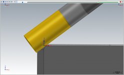
I've got a part, let's say it's a cube with .1 radius on each corner. This part is a 5 axis part. Ill preface this by saying I'm new to 5 axis. But I got the idea I want to mill the radius with the side of a flat end mill, tangent to the radius. Almost like swarf milling, but every few degrees.

The closet I've come is multiaxis flowline with a 90 degree side tilt, this method drives the corner of the tool into the cut, obviously I want the corner of the tool well below the contact point.

I will also say I know there are dozens of alternate methods of cutting a similar feature, however ide like to know how to do this method.

Thanks
 
I'm having a hard time visualizing the part. Can you toss in a paper sketch?
But if you are considering flowline, have you tried Morph? Hands down 100% better than flowline.
 
Not seeing the part I would say that is a 3 axis toolpath. Mastercam does not have a toolpath to do what you describe as there is no point to machining a radius that way. One of the big advantages in 5 axis machining is to not use it if you don't need it.

Paul
 
The closet I've come is multiaxis flowline with a 90 degree side tilt, this method drives the corner of the tool into the cut, obviously I want the corner of the tool well below the contact point.

Not sure about mastercam, but surfcam will do that as well. There's an axial shift option where you can raise or lower the tool along the tool axis.
 
I'm having a hard time visualizing the part. Can you toss in a paper sketch?
But if you are considering flowline, have you tried Morph? Hands down 100% better than flowline.

Get ready for the greatest sketch of all time. I call this one ' I've been awake for 10 minutes"

Perhaps for the sake of argument it might be easier to say this is a 4 axis part, does this childlike drawing clear anything up?

Thanks!
 

Attachments

  • IMG_20190116_054412.jpg
    IMG_20190116_054412.jpg
    83.9 KB · Views: 219
Not seeing the part I would say that is a 3 axis toolpath. Mastercam does not have a toolpath to do what you describe as there is no point to machining a radius that way. One of the big advantages in 5 axis machining is to not use it if you don't need it.

Paul

I fully agree with you, from the description this seems like an easy problem. The part is more complicated then I've described. I also know about 6 different ways around the problem. However I am the type of guy that really wants to know how to do something, if I feel like I should be able to do something I will almost always try to figure out how to do it, even if it's not the best method for this particular part, I know it will come in handy one day.

Thanks for the help!
 
I've got a part, let's say it's a cube with .1 radius on each corner. This part is a 5 axis part. Ill preface this by saying I'm new to 5 axis. But I got the idea I want to mill the radius with the side of a flat end mill, tangent to the radius. Almost like swarf milling, but every few degrees.

The closet I've come is multiaxis flowline with a 90 degree side tilt, this method drives the corner of the tool into the cut, obviously I want the corner of the tool well below the contact point.

I will also say I know there are dozens of alternate methods of cutting a similar feature, however ide like to know how to do this method.

Thanks

Curve 5X will do what you want...why you want to is another discussion I guess, eg. you're gonna have clearance issues.

You will have to create some extra curves (curve slice of the rad), add those to the cut pattern, add the surface to axis control, tilt the tool as needed, set the vector depth as required to get the needed portion of the endmill onto the surface.

1.jpg 2.jpg 3.jpg
 
I tried this in Fusion 360 using 5-axis "Flow". I was able to successfully generate the tool path along 4 edges of the cube, but haven't been able to figure out how to do an axial shift in order to use a different portion of the cutting tool. I suppose in a specific move like this, nothing would prevent one from simply changing the tool length offset (and clearance heights) since the end face of the end mill is never used.


5x.jpg
 
Get ready for the greatest sketch of all time. I call this one ' I've been awake for 10 minutes"

Perhaps for the sake of argument it might be easier to say this is a 4 axis part, does this childlike drawing clear anything up?

Thanks!

Yes, that sketch is fine.
It looks like you want to travel down the length of the stock while forming the radius.
I would use either goose's way above or Morph.
 
Curve 5X will do what you want...why you want to is another discussion I guess, eg. you're gonna have clearance issues.

You will have to create some extra curves (curve slice of the rad), add those to the cut pattern, add the surface to axis control, tilt the tool as needed, set the vector depth as required to get the needed portion of the endmill onto the surface.


So my thoughts on the subject are as follows, for this particular part I cant simply profile it with an end mill nor can I use a radius cutter, this feature would traditionally be milled with a ball end mill. However at this particular point in the program I've got a flat end mill in my spindle, and it would be ideal to finish this radius at this point.

With all that being said I'm under the impression that the larger the ball end mill used the smaller the scallop height, and the fewer passes I need to take, so if I apply that same concept to a side of an end mill I should be able to take maybe 6 passes to generate a decent radius with a very small scallop. And if my first and last passes are maybe 2 degrees off each wall clearance won't be an issue.

This is my thought process, I'm happy to be told why it won't work, or why it's a bad idea, that's why I am here, but from where I'm sitting it seems legitimate... Ish.


I don't see how that would apply with the toolpath you are looking at. A 1/4" endmill and a 1/2" would leave the same finish, depending on stepover since you are using the side of the tool... Unless I have misunderstood something... :willy_nilly:

Based on the napkin sketch, I don't see why a 3d toolpath with a ball endmill won't work, just 'index' the part 4 times ... :Ithankyou:
 
So my thoughts on the subject are as follows, for this particular part I cant simply profile it with an end mill nor can I use a radius cutter, this feature would traditionally be milled with a ball end mill. However at this particular point in the program I've got a flat end mill in my spindle, and it would be ideal to finish this radius at this point.

With all that being said I'm under the impression that the larger the ball end mill used the smaller the scallop height, and the fewer passes I need to take, so if I apply that same concept to a side of an end mill I should be able to take maybe 6 passes to generate a decent radius with a very small scallop. And if my first and last passes are maybe 2 degrees off each wall clearance won't be an issue.

This is my thought process, I'm happy to be told why it won't work, or why it's a bad idea, that's why I am here, but from where I'm sitting it seems legitimate... Ish.


...your welcome for the toolpath help I guess?
 
So my thoughts on the subject are as follows, for this particular part I cant simply profile it with an end mill nor can I use a radius cutter, this feature would traditionally be milled with a ball end mill. However at this particular point in the program I've got a flat end mill in my spindle, and it would be ideal to finish this radius at this point.

With all that being said I'm under the impression that the larger the ball end mill used the smaller the scallop height, and the fewer passes I need to take, so if I apply that same concept to a side of an end mill I should be able to take maybe 6 passes to generate a decent radius with a very small scallop. And if my first and last passes are maybe 2 degrees off each wall clearance won't be an issue.

This is my thought process, I'm happy to be told why it won't work, or why it's a bad idea, that's why I am here, but from where I'm sitting it seems legitimate... Ish.

If you want to go off on this tangent...yes, the flat endmill will produce less scallop than a ball mill given the same number of passes. This has typically been a ball mill feature since typically shops did not have access to 5x machines, as well the simplicity of a 3X cut, rigidity of the 3X cut, edit-ability of a 3X path, this has been a no brainer. Even more simple is a 2X cut. Form tool with a 2D contour. This would also be the fastest cut and no scallop. You need to decide what's important for your job. Using a 5x machine for a part that could be done on a bridgeport, that's your call.
 
If you want to go off on this tangent...yes, the flat endmill will produce less scallop than a ball mill given the same number of passes. This has typically been a ball mill feature since typically shops did not have access to 5x machines, as well the simplicity of a 3X cut, rigidity of the 3X cut, edit-ability of a 3X path, this has been a no brainer. Even more simple is a 2X cut. Form tool with a 2D contour. This would also be the fastest cut and no scallop. You need to decide what's important for your job. Using a 5x machine for a part that could be done on a bridgeport, that's your call.


Nice thanks man I appreciate the feedback. I'll give the curve 5 a try. That will be the fastest way to do this particular part. It's got to go in the 5 axis anyway!
 
I don't see how that would apply with the toolpath you are looking at. A 1/4" endmill and a 1/2" would leave the same finish, depending on stepover since you are using the side of the tool... Unless I have misunderstood something... :willy_nilly:

Based on the napkin sketch, I don't see why a 3d toolpath with a ball endmill won't work, just 'index' the part 4 times ... :Ithankyou:


I see the confusion, I mean to say if this were done the traditional method with a ball end mill the larger diameter would help. You are correct in that my scenario the diameter won't make a difference. Thanks!
 
Brian, you are correct.

you can mill the radius of the cube with any section of the end mill in mastercam with the 5 axis suite of toolpaths. The side will give you the best finish using fewer passes.

the advantage of doing it this way is that it is much faster to produce a smoother toolpath.

in 2019 you can even mill with lens shaped tools like this in full 5 axis.

What's New in 219: Mastercam Multiaxis Full Feature - YouTube
 
That is one of the correct methods...

5x Flowline will work well with 90 or close to 90 side tilt. Parallel should work out too, but you have to switch to one way.

The multi axis suite you can use the same concept with a bunch of them, tilt the tool 90 or so on on the axis control screen. You will also have to set the collision control to move away from the tool when it detects a collision with the surface and the tool.
This is great! I'm going to get back into this part tonight, I'm definitely starting with your suggestions. I really appreciate the help. Do you find yourself using this method often?


Back
Top