What's new
What's new

Problem with lathe tool compensation in Fusion

MMC Design

Aluminum
Joined
Jan 2, 2007
Location
VA
New to CNC programming. I am trying to understand tool offsets. I am using HSMWorks to generate code for a ProtoTrak lathe. The parts are consistently coming out a tool radius undersized. I set HSMWorks to build the compensation into the code (IN COMPUTER setting). The code it cranks out sets G40 and then puts the final tool path directly on the part final dimension. The lathe runs the tool on TOOL CENTER compensation, which seems to put the tool path on the center of the nose radius as opposed to the virtual tip. What can I do to correct the issue, or am I bound to edit the code and insert G41 and G42 as appropriate.

Mike

I don't know about Fusion, but in NX when making a lathe tool you have to select your tracking point for that tool. It defaults to the center of the radius and you have to select the leading edge of your insert.
 
I have never had luck posting lathe code from Fusion and getting radii correct. I'm sure I am doing something stupid with the tool nose direction or shape or whatever, but I end up just posting "in control" and then using the nose type and radius offsets in the controller. I usually still have to tweak the code a little bit using larger or smaller R values. I think there is quite a bit of variation in tool geometry for lathe inserts which compounds with whatever I am doing wrong...
 
Thanks for the replies.

The Fusion help desk is pretty adamant that their software is correct in putting the tool path right on the part surface when G40 is set.

That doesn't make sense to me based on my understanding of the definition of G40, but what do I know, I am new at this.

The only way that I can make Fusion work is if I can set the tool center to the center of the tool radius somehow instead of the tangent corner of the tool or to manually edit the post and add G41/G42 as needed so the lathe puts the tool in the right spot.

Mike
 
Think I found the solution

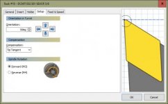
I think I found the solution to my problem. Someone pointed out to me that you can change the compensation method in the tool set up, which makes sense.

The problem was the tool center method used to calculate the toolpath. It turns out Fusion/HSMWorks has a pull down in the tool set up. The tool was using the default compensation method of TIP TANGENT in the set up
Tip Tangent.jpg

Which gave me these tool paths, that ran the tool right along the part surface, which caused my lathe to cut the parts undersized because of the way the lathe handles the compensation.
Tip Tangent tool path.jpg

By going into the tool setup tab and changing the compensation to TIP CENTER, the problem seems to be solved, at least by looking at the generated toolpaths.
Tip Center.jpg

Now the tool path is off of the part by the tip radius. This should give me a good result.
Tip Center tool path.jpg


Mike
 
I think I found the solution to my problem. Someone pointed out to me that you can change the compensation method in the tool set up, which makes sense.

The problem was the tool center method used to calculate the toolpath. It turns out Fusion/HSMWorks has a pull down in the tool set up. The tool was using the default compensation method of TIP TANGENT in the set up
View attachment 333643

Which gave me these tool paths, that ran the tool right along the part surface, which caused my lathe to cut the parts undersized because of the way the lathe handles the compensation.
View attachment 333642

By going into the tool setup tab and changing the compensation to TIP CENTER, the problem seems to be solved, at least by looking at the generated toolpaths.
View attachment 333645

Now the tool path is off of the part by the tip radius. This should give me a good result.
View attachment 333644


Mike

Assuming you touch your turning tool off in X and Z as per normal, using "in computer" (as opposed to "in control") works fine if all your features are orthogonal (no tapers, geometry-critical chamfers, curved profiles etc) because you can still comp the tool in X and Z on the machine. That means if you're taking a cut in Z at a fixed X value, it'll be completely fine with Tip Tangent and In Computer settings. For those orthogonal features, it will also post geometrically correct g-code (ie facing off will be done at Z0.000) but for any movement using both X and Z axes simultaneously (non-orthogonal features) if using "in computer" the code will shift the tool's imaginary tip (what the control records when you touch it off as though you have a completely square insert with no radius) in whichever direction Fusion determines that it needs to, so if you have a taper that goes from say X0.500 Z0.000 to X1.000 Z-0.250 (a 45 degree chamfer) it will offset the coordinates in the g-code in either X or Z (or both) to ensure that the radiused tip of the tool stays in contact with the taper.

It will have a potential error on non-orthogonal (tapered/compound) surfaces that is whatever the error in the insert radius is, because as above, it'll adjust the X and Z values for tapered surface in the G-code. By this I mean that if your G-code is spat out thinking you've got say an 0.008" radius on the insert but you're actually using an 0.016" TNR then it'll be slightly off on those surfaces where it is not just cutting in one axis only (ie only a Z movement, or only an X movement. This means that if you're using In Computer compensation, you must repost the code if you use a different insert radius. If all features are orthogonal, there's no radii or tapers, it doesn't matter what the tool nose radius is.

If you use "in control" then it generates G41/42 compensation codes that basically tell the controller exactly what the part geometry is, rather than where to put the insert based on where it thinks the imaginary tip is, if there were a zero radius, based on where you touched off in X and Z. In those cases the G-code should always exactly match the actual part geometry because the G41/42 codes tell the controller to consider the tool nose radius which you enter at the control (if G41/42 are not active, ie if G40 is active, then tool nose radius is ignored by the control, it just assumes the TNR is zero).

In my opinion, "tip tangent" is always the correct compensation to use - using "tip" or "tip center" (or especially "insert center", wtf fusion) does not make sense in any case I can think of. I'd recommend steering clear of "in control" too for most applications because as someone else said, it can create all kinds of errors/alarms (like if you tell the tool to cut in Z then up/out in X without specifying a linking radius) because it is trying to match the tool radius in the control, to the specified geometry in the g-code, and obviously you can't actually get a radiused insert into a sharp corner. G41/42 are highly necessary with milling tools but mostly a waste of time for turning because you can already comp the tool in x and z to change size of a feature.

It is frankly confusing as hell though and Autodesk don't do a very good job of explaining it IMO. There is a reasonably good explanation of all the options here - Solved: Tool tip used in turning, right and wrong choice. - Autodesk Community
 
It will have a potential error on non-orthogonal (tapered/compound) surfaces that is whatever the error in the insert radius is, because as above, it'll adjust the X and Z values for tapered surface in the G-code. By this I mean that if your G-code is spat out thinking you've got say an 0.008" radius on the insert but you're actually using an 0.016" TNR then it'll be slightly off on those surfaces where it is not just cutting in one axis only (ie only a Z movement, or only an X movement. This means that if you're using In Computer compensation, you must repost the code if you use a different insert radius. If all features are orthogonal, there's no radii or tapers, it doesn't matter what the tool nose radius is.

If you use "in control" then it generates G41/42 compensation codes that basically tell the controller exactly what the part geometry is, rather than where to put the insert based on where it thinks the imaginary tip is, if there were a zero radius, based on where you touched off in X and Z. In those cases the G-code should always exactly match the actual part geometry because the G41/42 codes tell the controller to consider the tool nose radius which you enter at the control

I'd recommend steering clear of "in control" too for most applications because as someone else said, it can create all kinds of errors/alarms (like if you tell the tool to cut in Z then up/out in X without specifying a linking radius) because it is trying to match the tool radius in the control, to the specified geometry in the g-code, and obviously you can't actually get a radiused insert into a sharp corner. G41/42 are highly necessary with milling tools but mostly a waste of time for turning because you can already comp the tool in x and z to change size of a feature.

How on earth do you square those statements up?
First, you ( absolutely correctly) state that using "in control" compensation lets the machine decide the actual toolpath based on what it has in it's offset registers.
Then, you ( absolutely incorrectly) state to stay clear of "in-control" compensation for reasons ... well all the wrong reasons actually.

Using" in-control" will :
1: Always give correct dimensional results as long as the tool info is properly defined in the control's offset register( tip radius and direction )
2: Will NOT cut a feature if the properly defined tool is too big to do so.
3: Will never need re-posting if you decide that a .032 R finish tool give a chattered finish and switch to a .007R instead on the fly.


I'd recommend steering clear of "in control" too for most applications because as someone else said, it can create all kinds of errors/alarms

I would submit to you that if a CAM generated code using "in-control" strategy raises an alarm ( ANY alarm ), then that CAM program sucks at creating lathe programs.
Or, just sucks in general!

Period, end of story!


Back
Top