What's new
What's new

SolidWorks CAM / Camworks with double station vises

jj80909

Aluminum
Joined
Sep 16, 2015
Hello,

I am seeking some help with SolidWorks Cam / Camworks. I am trying to figure out the workflow for setting up a simple part at WCS G54 (with all required toolpaths) and then copying / transforming / translating / rotating the setup to allow machining the same part in 3 dual-station vises (6 parts total).

We currently setup the dual-station vises with the “front” location of each of the three vises as “even” (WCS G54, G56, and G58) and we designate the “back” locations as “odd” (WCS G55, G57 and G59). The CAM program for the front (even) WCS are just copies of the G54 part, while the back (odd) WCS are essentially rotated with the signed movements of X & Y flipped.

We currently use HSMWorks to program one setup of the part at G54 and then use the software to "copy" the toolpaths for WCS G56 and G58. This gives us one setup that contains the toolpaths for the 3 “even” WCS.

Next we copy the “even” generated setup, and change the initial WCS to G55 with copies at G57 and G59. This gives us a second setup that contains the toolpaths for the 3 “odd” WCS.

So we end up with two setups and we post-process both to create a program that cuts all six parts in one cycle (one at each WCS - G54 through G59).

The HSMWorks software allows this easily by checking a few boxes in the software.

We would like to move to Solidworks Cam (rebranded Camworks), but I have yet to figure out how to do the setups. I would like to find the workflow that is the best / easiest way to do this, but I have yet to figure it out.

I would think there are plenty of shops using Camworks and dual-station vises to make multiple parts in a cycle. Is anyone out there a Camworks or SolidWorks CAM user that can shed some light on this? Any help is appreciated.
 
So if I understand correctly you want to have two two different orientations- one for the front parts and one for the back parts.

The orientation part is set by clicking the "Coordinate System" in your cam works tree. Once in there you can specify where zero is on your part and what direction x, y, and z point. Once you set this click on "Setup" in the tree and then click on the offset tab and specify your work coordinate (G54... etc). Then once that is set go ahead and post it. Then set your work coordinate again to say G56 then post it and then again for G58.

Now go back to respecify your coordinate system for your back orientation then post it three times again with the various work offsets.

The only thing about this approach is it does a whole part with all the tool changes then does the second part etc. If you have SW CAM Pro you could set the whole thing up as an assembly and it would do each operation on each part then do the tool change.

I am using it with some dual station vises but I always use them for the different ops. For one of my machine I am dong 4 operations with two double vises.
 
Pete Deal, thanks for the reply, but I am hoping there is an easier / more seamless way to do this that minimizes tool changes and manual editing of posts. It would be nice if this can be accomplished on one part so the step of making an assembly can be skipped.

thunderskuck, HSMWorks is great for simple 3D stuff and I would like to continue using it, but it looks like the writing is on the wall and autodesk will kill it off soon. I am looking for a solution for the near future. I have a single user seat of Fusion360, but I only use it for the HSMWorks entitlement...I do not want to go with cloud based software.
 
Well since I haven't done exactly what you're trying to do I'm not an authority here.

Many of my parts are made in strips though which has some similarities and for this I make them in assemblies. From what I know about the system I think what you want to do would also be done via assemblies. An assembly of three parts. The two orientations might need to be two different configurations since they would need different origins. Working in assembly mode is really no burden to me.

I didn't watch the whole video but this appears to address what you're trying to do- CAMWorks - Assembly Machining 101 Pt. 2 - YouTube

Regarding SW CAM I pretty much use it every day and it does what I need. I only tried Fusion briefly but their model is not for me so left pretty quickly and won't give Autodesk any more money in this lifetime. I guess my biggest complaint is that even with SW CAM Pro, which I have and maintain my license, it's still a 2.5d system. The few 3d strategies they toss in are pretty worthless, at least for me they have been. Seems like they could add a little more 3d capability.
 
Last edited:
thunderskuck, HSMWorks is great for simple 3D stuff and I would like to continue using it, but it looks like the writing is on the wall and autodesk will kill it off soon. I am looking for a solution for the near future. I have a single user seat of Fusion360, but I only use it for the HSMWorks entitlement...I do not want to go with cloud based software.

I’m not sure the writing is on the wall per-say; it’s integral to both Fusiom360 and Inventor, just depends on if they want to kill the Solidworks integration. I think a huge amount of subscriptions to F360 are just like you and me: we just want HSMworks. But maybe you’re right too.

I should say I really enjoyed Inventor. It’s really not all that different from Solidworks, but has a different set of bugs. I still default to Solidworks.

Haven’t used CAMworks deliberately, but played with it enough to know it would work in a pinch.
 
I worked at a shop where the programmer did it as an assembly with one work offset. Depending on what we were making, we either used soft jaws to locate parts, or used a programmable pin to slide part up against. There was a custom macro at the top where you would plug in the number of vices used and the distance between the vices. Viola!

The way the macro worked, basically it shifted the work offset a certain number of inches how ever many times you wanted it to. But it was fancy because it like someone previously mentioned running each tool before a tool change, it did that, rather than completing individual parts.
 
I know this about a month old, but if you haven't found a way.
There's a couple ways to do what you are trying to do. The quick and easy way

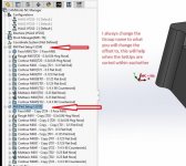
Right click on your machine part set up, copy set up, you'll see it creates an additional machine part setup under all your generated tool paths, highlight all your generated tool paths (click on the top one, hold shift and click on the last one) and hold down shift (might be CTRL, I'm not next to software to verify) and drag them all down to the new machine part set up, it should create a copy of all the tool paths, generate the tool paths.

You should now have two of the exact same set ups and generated tool paths. Right click on your 2nd machine parts set up and unlink it from the first one, and then change the WCS to 55.

You can do this as many times as you need G55, 56, 57, and so on.

You now have each of your coordinate locations programed, you have the option to SORT OPERATIONS. You have to make sure you have the Machine on your tree selected to allow it to sort all operations across set ups. Once you select SORT OPERATIONS you'll have some options, select sort operations across set ups and then the next tab, sort by tool and organize your tools in the order you would like.

That will allow it to run T1 on all coordinate systems before tool changes, you can also leave it as is and run each coordinate system separately.


You can get fancy and use Assembly machining and bring the part in multiple times, its a little bit more of a set up to do so.

If you have any questions feel free to respond. I can upload step by step photos if needed. Hope this helps. Been running CAMWorks for over 10 years if you have any other questions.
 
It's not my thread but bthomas7408 - thanks for that! Very good info. It's funny I'm a 15 year or so solidworks user and 3 year now with SW CAM. I know what I know pretty well but there are so many ways to do things that I have not explored. You taught me a few things with that post.
 
No problem! There's multiple ways to do the same thing. You can also create another Mill Part Set Up in your Feature Tree and select all the operations from your first Set Up and right click, Copy Features and select the second Mill Part SetUp and there's a box you can check that will allow it to also Copy The Operations Generated Toolpaths.

I always copy the CAMWorks configuration when doing either way so I have my default 1 part set up and tool paths and then my next Configuration is where I will create multiple offsets and sort the toolpaths. That way it's easy to go back to one part if ever needed and I also have my multiple parts tool paths available as well.
 
Thanks! Copying the setups and operations is something I haven't done but seems straight forward enough. What I didn't know was that it was possible to sort operations over setups and how to do it. Very good to know. Thanks again.
 
bthomas7408, thanks for all the info.

To give this a try, I created a test part with two SolidWorks work coordinate systems : G54 & G55.

I created a CW setup for G54 that has two operations / tools and due to your help, I was able to create a second setup for G55.

However, I'm stuck on getting the definition of G55 set correctly or getting it to post toolpaths to G55.

To start, I right click "Mill Part Setup2 [G55]" and select "Edit Definition".

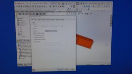
This brings up the "Part Setup Parameters" window and I have tried different combinations on the "Origin", "Axis", and "Offset" tabs.

With the combinations I have chosen, I do get the proper work coordinate to display when I select Mill Part Setup2 [G54] or Mill Part Setup2 [G55]...they display as (WC = G54) and (WC = 55) on screen.

Even though it appears the two setups are correct, when I post, I only get G54 output.

It's probably something simple that I am doing wrong...any help?

Could it be something in the machine setup or post-processor file? I'm using a junk Haas post-processor from my VAR (you would think their Haas post would at least use G53s).
 

Attachments

  • G54 WCS.jpg
    G54 WCS.jpg
    99 KB · Views: 31
  • WC G55.jpg
    WC G55.jpg
    100.6 KB · Views: 38
  • G55 Edit Definition.jpg
    G55 Edit Definition.jpg
    98.5 KB · Views: 31
  • Origin Tab.jpg
    Origin Tab.jpg
    97.8 KB · Views: 28
  • Axis Tab.jpg
    Axis Tab.jpg
    98.7 KB · Views: 25
bthomas7408, thanks for all the info.

To give this a try, I created a test part with two SolidWorks work coordinate systems : G54 & G55.

I created a CW setup for G54 that has two operations / tools and due to your help, I was able to create a second setup for G55.

However, I'm stuck on getting the definition of G55 set correctly or getting it to post toolpaths to G55.

To start, I right click "Mill Part Setup2 [G55]" and select "Edit Definition".

This brings up the "Part Setup Parameters" window and I have tried different combinations on the "Origin", "Axis", and "Offset" tabs.

With the combinations I have chosen, I do get the proper work coordinate to display when I select Mill Part Setup2 [G54] or Mill Part Setup2 [G55]...they display as (WC = G54) and (WC = 55) on screen.

Even though it appears the two setups are correct, when I post, I only get G54 output.

It's probably something simple that I am doing wrong...any help?

Could it be something in the machine setup or post-processor file? I'm using a junk Haas post-processor from my VAR (you would think their Haas post would at least use G53s).


right click on your g55 set up and go to the offsets tab. Where it says work coordinates you have to change it to 55 under the start value. select the assign and the lower dialog box you will see the offsets change to 55.

you can make several offsets/ coordinate systems but you have to assign each one to a different zero set or it will default to the last one.
 
Well since I haven't done exactly what you're trying to do I'm not an authority here.

Many of my parts are made in strips though which has some similarities and for this I make them in assemblies. From what I know about the system I think what you want to do would also be done via assemblies. An assembly of three parts. The two orientations might need to be two different configurations since they would need different origins. Working in assembly mode is really no burden to me.

I didn't watch the whole video but this appears to address what you're trying to do- CAMWorks - Assembly Machining 101 Pt. 2 - YouTube

Regarding SW CAM I pretty much use it every day and it does what I need. I only tried Fusion briefly but their model is not for me so left pretty quickly and won't give Autodesk any more money in this lifetime. I guess my biggest complaint is that even with SW CAM Pro, which I have and maintain my license, it's still a 2.5d system. The few 3d strategies they toss in are pretty worthless, at least for me they have been. Seems like they could add a little more 3d capability.


Both modes, assembly and part mode have their advantages and what ever is easier for you I would use more but some of these single parts I program in part mode, it just means I have to change the orientation of the work plane when programming in part mode. In assembly mode it is easier to see how you lay out the parts and setup your work offsets.
 
Well since I haven't done exactly what you're trying to do I'm not an authority here.

Many of my parts are made in strips though which has some similarities and for this I make them in assemblies. From what I know about the system I think what you want to do would also be done via assemblies. An assembly of three parts. The two orientations might need to be two different configurations since they would need different origins. Working in assembly mode is really no burden to me.

I didn't watch the whole video but this appears to address what you're trying to do- CAMWorks - Assembly Machining 101 Pt. 2 - YouTube

Regarding SW CAM I pretty much use it every day and it does what I need. I only tried Fusion briefly but their model is not for me so left pretty quickly and won't give Autodesk any more money in this lifetime. I guess my biggest complaint is that even with SW CAM Pro, which I have and maintain my license, it's still a 2.5d system. The few 3d strategies they toss in are pretty worthless, at least for me they have been. Seems like they could add a little more 3d capability.

I do quite a bit of 3D milling with my CAM PRO and have never had an issue getting it to do exactly what I need with odd surfaces. I don't use much of the "3 Axis Mill Operations" I always create my surfacing toolpaths with the "Multiaxis Mill" operation and under the PATTERN tab you have quite a bit of options for Patterns to use and control.
 
I do quite a bit of 3D milling with my CAM PRO and have never had an issue getting it to do exactly what I need with odd surfaces. I don't use much of the "3 Axis Mill Operations" I always create my surfacing toolpaths with the "Multiaxis Mill" operation and under the PATTERN tab you have quite a bit of options for Patterns to use and control.

Same I find multiaxis mill to be much more powerful with surface extends etc. I try to use it for most 3D stuff.
 
I do quite a bit of 3D milling with my CAM PRO and have never had an issue getting it to do exactly what I need with odd surfaces. I don't use much of the "3 Axis Mill Operations" I always create my surfacing toolpaths with the "Multiaxis Mill" operation and under the PATTERN tab you have quite a bit of options for Patterns to use and control.

by "CAM PRO" do you mean solid works CAM PRO or is the CAM PRO you're referring to a level of Camworks? The reason I ask is that I've never seen a "Pattern Tab" in solidworks cam pro. I maybe need to look again.


Back
Top