HappyHapgood
Plastic
- Joined
- Nov 28, 2020
I've been pulling my hair out trying to model the CAM in Fusion360 for what seems to be a simple part. It's small cylindrical puck with some machining on both sides. I'm "self-taught" with Fusion360 and feel reasonably comfortable on the CAD, but maybe I messed up something in the model?
But the real problem (aside from the fact that I am also very green at machining and CAM) is the CAM for a curved slot in my part.
The puck has a center bore, four holes in around the bore, and some passages. Most of the passages are flat-bottomed and I finally cheated my way towards successfully machining the cylindrical one (it's a 3/16" wide channel, but it wouldn't allow a 3/16" flat end mill tool, so I cheated on the dimension by saying it was 0.1874 instead of 1875... then that worked). I've already tested it on the mill and it was spot on.
FYI, the material is Delrin 100AF
Okay, so the problem is that darn rounded slot. I have tried what seems like 100 permutations and combinations of strategies and I just can't get there. Fusion360, with me at the keyboard, refuses to mill the part of the rounded slot closest to the center. I've tried multiple ball-nose endmills, I've tried drilling it. But all the strategies want to "lift" the tool as it gets closer to the center and create a shelf. And... even though I have REST machining, it also always wants to go into the center bore, even though I believe I've completely machined the bore already.
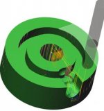
I've pasted an image of the part below, and I'll work on uploading the fusion file too.


Any and all guidance and help is appreciated!
But the real problem (aside from the fact that I am also very green at machining and CAM) is the CAM for a curved slot in my part.
The puck has a center bore, four holes in around the bore, and some passages. Most of the passages are flat-bottomed and I finally cheated my way towards successfully machining the cylindrical one (it's a 3/16" wide channel, but it wouldn't allow a 3/16" flat end mill tool, so I cheated on the dimension by saying it was 0.1874 instead of 1875... then that worked). I've already tested it on the mill and it was spot on.
FYI, the material is Delrin 100AF
Okay, so the problem is that darn rounded slot. I have tried what seems like 100 permutations and combinations of strategies and I just can't get there. Fusion360, with me at the keyboard, refuses to mill the part of the rounded slot closest to the center. I've tried multiple ball-nose endmills, I've tried drilling it. But all the strategies want to "lift" the tool as it gets closer to the center and create a shelf. And... even though I have REST machining, it also always wants to go into the center bore, even though I believe I've completely machined the bore already.
I've pasted an image of the part below, and I'll work on uploading the fusion file too.


Any and all guidance and help is appreciated!


