What's new
What's new

American Tool Works Lathe

Tatertots

Plastic
Joined
Feb 11, 2018
I have an old American Tool works lathe that was saved from scrap by my father in law many years ago and it has been with a friend of ours getting occasional use until he needed the space and it moved to my shop last week.

I would like some help with the location of the serial number so I can find manufacture date, manuals, etc. It appears to have originally been flat belt drive, but has had a variable speed system bolted on top of the head stock which seems to work quite well. It is 24" swing and about 10' from chuck to tailstock, and it has a 22" four jaw that will replace the tiny three jaw currently mounted.

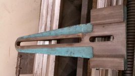
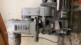
It has a taper attachment (neither of my other lathes has one) that is missing some components - if anyone has one of these and is willing to share pictures or specs of the pieces I need it would be appreciated. I am missing the piece(s) that fit between the first and the second pictures. The piece in the second picture tucks under the back of the cross slide - it is missing its gib.

Looking forward to getting this machine settled in and leveled Thanks!
 

Attachments

  • 20181004_191752.jpg
    20181004_191752.jpg
    91.6 KB · Views: 303
  • 20181004_191806.jpg
    20181004_191806.jpg
    94.3 KB · Views: 273
  • 20181004_191927.jpg
    20181004_191927.jpg
    94.7 KB · Views: 320
  • 20181004_191840.jpg
    20181004_191840.jpg
    97.8 KB · Views: 1,034
Won't be any manuals - they were not doing such that far back

Serial right end, stamped in to machined cast iron on FRONT VERTICAL FACE of front way.

It will be a five digit number. Serial book - that only goes back to 1920 - has 51XXX for that year.

In other words, you may have to squat down to see it:)

Here is an early scan, thanks to Greg Menke for hosting this for me. Taper Attachment on Page 2

http://pounceatron.dreamhosters.com/docs/atw/atw-1919-product-guide.pdf
 
Hello:
The old lathes that use a screw down mechanism to engage the feed cone clutches need to be used with caution. The clutch can tighten itself under a heavy load and make it very difficult to disengage. This can be a problem if you are working toward a step and the clutch is engaged. The clutches should only be engaged just enough to prevent slipping. Any additional tightening may cause the clutch to lock in position.

Robert
 
I appreciate the warning... I have noticed they can be a bit sticky just in the little bit I have tried things out.
 
It is number 35496, so it might be even older than my 3B plain K&T horizontal from 1914 or 1915... it was 4 of lot 453 when lot 671 was 1920 as well. I seem to gravitate to machines of this era... Thanks for the great link to the information on this lathe. I seem to have another piece of history rumbling around the shop making metal shavings!
 
It is number 35496, so it might be even older than my 3B plain K&T horizontal from 1914 or 1915... it was 4 of lot 453 when lot 671 was 1920 as well. I seem to gravitate to machines of this era... Thanks for the great link to the information on this lathe. I seem to have another piece of history rumbling around the shop making metal shavings!

Greg's web page has a ATW scan from 1911 - not much different on cone heads, just more antique looking gear heads. I am always amazed at the early-ness and intensity of gear head developments

http://pounceatron.dreamhosters.com/docs/index.html

Greg also has my K&T 1917 in case you have not seen it
 
Thats an early teens High Duty (by way of the circa 1919 Erecting/Operating guide associated with serial # 49568). The High Duty series of machines were manufactured from approx 1911 thru the early 1940's, yours is a 1st gen. Over the years the design evolved gradually, improving in specification (antifriction bearings etc) and casting quality. I had a 1912 vintage 14" High Duty for some time before I gave that away and am using a 1936 12" now.

I've not heard of any dimensioned drawings of these machines though some general drawings exist, sold by Bourn & Koch but they are not thorough- I'll look through the book and see if the taper attachment sliding block is shown in any detail. My current ATW has the telescoping cross slide feature so is not directly applicable, my older ATW used the same taper design as yours. IRC it was s simple block with dovetail and gib to match the taper way, with a tapped hole on top for a bolt to lock the cross-slide. The cross-feed nut must be detached from the cross-slide by removing the bolt that fastens them together, thus the cross-slide is free of the feed screw and, free to slide, traversed by the taper attachment.
 
Have gotten a tapered gib made for the piece that attaches to the cross slide and it is in place and working smoothly. The last piece of the puzzle is the missing sliding block for the taper way. The taper way is square sided rather than a dovetail. I need some guidance on design... would it use a square sided but tapered gib adjusted end to end with screws, or a flat gib that is adjusted with set screws from the side? Would the gib side be the side away from the lathe? I appreciate any pictures or thoughts on this... all the ones i can find only use a dovetail. Thanks much for the help.
 

Attachments

  • 20181011_224225.jpg
    20181011_224225.jpg
    86.4 KB · Views: 98
  • 20181011_224511.jpg
    20181011_224511.jpg
    92.6 KB · Views: 122
P&W Model C used inverse of block on tongue and instead had block in "groove". As can be seen, item 57 is the gib and is on the front or operator side. A later version still had the block, but no gib on the block
 

Attachments

  • PW C TA Block.jpg
    PW C TA Block.jpg
    80.8 KB · Views: 91
Probably the easiest way to make one is to use a body with significantly wider U groove carrying a rectangular gib block rather than the usual thin gib strip. Usual side pusher screws to set the clearance but once set the gib block is held in place by screws running down from the top of the main body through suitable slots. Block needs to take tapped holes for the fixing screws and wide enough to be stable when pulled up, maybe 1/2" minimum. I'd probably go to 3/4".

You should have clearance between the top of the guide rail and the underside of the main body. Also between the bottom of the body and the guide rail carrier. A major advantage of these square sided taper turner guide systems is that the block can float vertically if need be so you don't need uber precision alignment in the horizontal plane. Which makes them far easier, and cheaper, to make than the double dovetail style. Obviously alignment is going to be close but maybe not perfect.

Clive

That sounds simple enough to make, and presents a very practical approach. Thanks for the suggestion!
 
Made the piece for the taper attachment as suggested by Clive603 above (bolts to be replaced by set screws once I get to town). Seems to be working perfectly... which brings up the next problem. The flat belt is slipping on all but the lightest cuts (tightening did not appreciably improve the situation) - appears to be a leather drive pulley and a synthetic belt material of some kind. Can a belt dressing product be used to reduce the slip? If so what is recommended - I have sticky sprays for v-belts but not sure of the advisability of using on a flat belt. Thanks again!
 

Attachments

  • image-20181113_220146.jpg
    image-20181113_220146.jpg
    85 KB · Views: 85
The flat belt is slipping on all but the lightest cuts

Tell us about spindle....

Turns freely by hand?
(A snap way to get spindle free from drive and cone pulley is to disengage the pin/bolt in the face of the bull gear - which is one of the steps in getting the lathe ready to use the back gears for the lower range of speeds)

Nice light bodied oil in spindle related cups/oilers? (Velocite #10 is made for this job)

Thumbnail shows pin/bolt location in another make. Not all are simple pins to pull -some have to be "undone" and slid over laterally
 

Attachments

  • pin for BG.jpg
    pin for BG.jpg
    19.2 KB · Views: 65
I checked the spindle and it turned smoothly without much drag. I rechecked the belt tension and the tightening mechanism was bound up... the resistance I felt was not the belt getting tight. Repairs made and belt now snug. I was able to successfully cut a Brown and Sharpe #12 taper on an arbor for my old mill without too much difficulty. Thanks for the help! I think the old gal is on her feet again.


Back
Top