What's new
What's new

Cinciportzilla hydraulic knee power problems

BigonUSA

Plastic
Joined
Jun 13, 2016
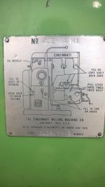
I got my first little mill that i finely got power to, it's a Cincinnati model # 467-14M1 - Serial # 2J34U5M-2 with a parts diagram MMA-63M-420357 From 6/5/1963, it was updated to it's current state in 1978 with the Bridgeport head and accessories and more, then shortly after that it was used very little as the company went to cnc machines.

Once under power it tried to power the table right and left and it moved a short distance no more. And it does not power any other direction. Reading some listings on here I saw a way to check pump pressure on the knee with a bypass line but had no flow ( oil reservoir full - middle port).

Next I saw it was recommended to drain and clean the reservoir, when I removed the bottom plate a 4" heavy spring fell out with one broken end. The parts listing I have is close to this but not the same. I believe it to be from the rapid traverse lever that I now noticed it flops down and not to the middle position.

Something else I saw looking over the diagrams I have that it showed a pressure switch of some type witch I think is on the lower right front of the knee, it has an relay / contact their. I saw only 2 of 3 wire hooked up and it does not move / engage when turned on.


Question 1 - will the broken spring cause no pressure?

Question 2 - do I need to drop the knee transmission to replace the spring?

Question 3 - should I Pull the pump housing off the left side of the knee?

Question 4 - is the pressure switch wiring right?


With this being my first Cincinnati mill I am learning a lot about this unite, but know I also have a lot to learn and any help would be greatly appreciated, I get time to work on it now and then but would like to bring it back to full usage as soon as I can.

Thanks in advance for any advice / help
 

Attachments

  • WP_20141217_001.jpg
    WP_20141217_001.jpg
    96.1 KB · Views: 263
  • WP_20150604_006.jpg
    WP_20150604_006.jpg
    91.3 KB · Views: 305
  • WP_20150522_020.jpg
    WP_20150522_020.jpg
    93.2 KB · Views: 266
  • WP_20150522_002.jpg
    WP_20150522_002.jpg
    96.6 KB · Views: 264
You have a no. 3 (410 - 14 ) MI universal mill. 1964 . Open the big door in the back and look up at the top left hand corner inside. Some have pressure switches there.
Send a picture of the spring. If the spring has a loop on each end, you lost the rapid traverse lever spring 114202.,The locking pin may have come loose on the rapid traverse clutch shaft. To fix that you have to drain the oil and drop the feed box to get to it. If you want, try the pump bracket, and see if you can located the shaft.
Column oil filler is inside the big door at right side middle.

You have knee and column oil pressures to check.


i
 
Last edited:
Yes the spring has / had loops on each end.

What does the rear pump do?

I thought the side knee motor ran the table x, y, z?

The original invoice gave that model#, but the machine tag says 407-14MI.
What does the MI stand for?

What should be my next step? Drop the gear box to get to the spring mount -
should I be looking at other things when I get it down?

Thanks
 

Attachments

  • IMG_20181227_173733.jpg
    IMG_20181227_173733.jpg
    100.6 KB · Views: 163
  • IMG_20181227_173746.jpg
    IMG_20181227_173746.jpg
    100.2 KB · Views: 160
  • IMG_20181227_173753.jpg
    IMG_20181227_173753.jpg
    101.6 KB · Views: 154
The Mi is the model , the 407, the 7 means the HP of the motor. Two pumps, one is for the column and the other is for the Knee. Do you have a manual ? What is the pub. number ? i can pull my manual.
Not sure what pin you have showing in your pic, The s spring looks like it lost part of the loop.
 
What is the pub # and where do I find it?

The service / parts Manuel I have looks like most of my machine but not all of it.

The pin you may be referring to my be the allenhead socket if its shinny.

Yes there is a broken end on the spring and I do think it's from the rapid traverse lever.

Does the parts diagram MMA-63M-420357 help any?
 

Attachments

  • WP_20150522_004.jpg
    WP_20150522_004.jpg
    93.1 KB · Views: 107
Last edited:
The Pub. No. is on the bottom of pages in the book or on the binder. Pub. M - XXXX; If you happen to get the timing fixed. Yo can move the speed dial numbers to the right spot. Just unlock the dial hold down. The reason the machine is the way it is now, your handle on the right has dropped down and is not in neutral. It may be in feed as it is now. rapid is up on the handle/ You have lost the spring that holds it in position.
 
The service & parts manual I got was an M-2410,on page 25 they list the removal of the gear box with the locking of the gears with a set screw for sinking it to the dial when reinstalling.
 
I will take a look. Usually I fine the high to low cross over and then put the speed to the lowest speed.
 
Last edited:
To Remove Feed Dial Assembly from Knee

I was trying to remove the front dial as per the Manuel I have -

Drive taper pin (280A) from lever. (See page 58. ) Remove two set screws (281A), (282A), through bottom of boss on knee. Remove set screw (277 A) from center of pinion (278A), screw in a 1/ 4 - 20 rod and pull feed dial assembly from knee.

Should the leaver slide off of the shaft after the pin comes out?

I took the two set screws out of the bottom ok, but what does the 1/4" rod do?
Do you just pull on it or do you screw it in to push something out?
 
Another comment on the model number. I breaks down as such:

4 = X travel, 40"+ (my No.4 is like 42")
07= hp (double digits because many had more hp)
14= width of the table (my No.4 has a 17-7/8" table they just called 18)

If you look at a lot of these model numbers you start to see a trend in standard table sizes and corresponding hp ratings.

The MI were a bit different than the standard Dial Type so might explain the narrower table with the 40" travel.
 
Removing the front dial

What is the trick for removing the front dial assembly, I got the 2 screws from the bottom.
I did not find any set screw inside the dial shaft, I screwed a long 1/4" bolt in to the shaft and pulled on it but it did not move.

It said to use threaded rod - does it need to push on something only being 1/4"?

Does the adjusting lever need to come off first as I have been soaking it and using a heat gun on it but it has not moved.
 

Attachments

  • WP_20150522_011.jpg
    WP_20150522_011.jpg
    93.7 KB · Views: 82
The shaft on the feed dial does not come out without taking the front bracket off. I was trying to say you can hold the shaft with something through the pin hole and push it forward to get the gear on the shaft to slip out of gear while holding it. Do not let it fall inside. You then can rotate the gear and pull the shaft back into gear. Keep doing that until you fine the right gear for all gears to work and the handle pin will locate the gear in place.You can also move the numbers in place on the dial to match with you speed and the lock it back.
I think this is the machine that has the shear key behind the speed dial. If so, make sure its ok. If sheared, the key needs to be made with the right grade of steel. If the key is made with the steel that is too hard, it will shear your shaft end. Then you have lost the shaft to repair or a new one made.
 
Last edited:
This machine does not have the shear key and the front bracket on this model does not come off. When you take 277A out, put a long screw of the same thread in the same spot. Then you can move gear 278A forward and out of the gear it runs with..
 
This machine does not have the shear key and does not have a front bracket. If your feeds don't work, you may have to drop the feed drive. What point are you at right now ?

Regards,
 
I got as far as heating the selector lever on the shaft with a propane torch to get it off but it did not budge yet. I had not gotten back to it because of a health issue, but I hope to get back on it next week
 
Feed dial will not come out of the knee that way. What i am saying is the 277 A set screw is out. put a long screw in the place of the set screw. Then you can go in with the shaft and it will go out of gear (288A. rotate the gear on tooth and pull it back into gear.rotate the gear a tooth at a time until you can get the timing back in place. Hang on to the long screw has you turn the shaft.
The rapid spring will have to be put into place with the gear box out. With it out you can check the timing of the speed selecter.
 
cmike

Dose the feed dial need to be removed to drop the gear box?


no ! Drop the oil.. The hex head taper pin will break the head off if not careful . use a socket to take loose. work it back and forth.Take out all but a few bolts. put a four X four board under the feed box and lower the knee down too it.. Take the remaining screws out. The gear box may need taping to break the seal. Raise the knee up to clear the gear box. pull it out.

Good luck


Back
Top