What's new
What's new

GEARS!!!???? Trying to learn what's in my K&T 2HL

Crank

Aluminum
Joined
May 21, 2009
Location
San Diego
GEARS!!!???? Trying to assign values (reverse engineer) what's in my K&T 2HL

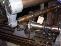
Got my 2HL universal with the vertical attachment. Luckily it came with the drive gear, however, that gear (a non-factory replacement) has no provision for drive dogs. Hence the gorilla torque used on the drawbar. I'm looking to find a good way to incorporate them into this one but decided I would learn about gears while I'm dealing with it.

What a Cluster@#$_. I have a 24T drive gear and a 23T driven splined shaft. I have no pitch gauges and trying to figure out all of the specs is overwhelming. Are there any "gearheads" that know how to speak this foreign tongue?

The root diameter of the 24T drive gear is 2.715", the O.D. is 3.208" the face is .986" and the angle of the gear teeth are between 28-29°. Can this be translated into a known value?

As these gears have a great propensity to go missing. I would like this post to provide information for those unfortunate enough to need a gear made from scratch by a gear company. There is a fair amount of chatter about 24T, 30T and even 32T but the formula for someone without the ability to make their own gears doesn't seem to exist.

I'll ask in advance if we could please keep the information on point for the specifics about these gears for the K&T 2HL so that it can be a solid reference for others. Other threads have wandered about the larger models and they didn't have much info to help either. Too many people wanted to add unrelated info and they went off the rails.

Here are a bunch of photos and I can get other measurements if I'm told what to look for.
Thanks

Mark
db16681c6ac3c32b028846d6894d6b1b.jpg
7c27fd74a81a4cdf5446e7c60c34da6f.jpg
7b57053a9600d43474dd2e607fbddeab.jpg
e7960b0a2a6b1aa8daa34aa885f2c745.jpg
24fd3183391fb52770ab7503714cfba2.jpg
aa30b7d24707251e0766b1257d810755.jpg
fc53725d9c9b6e7cdc06f80c9e7d2e47.jpg
885a59f47154c3a96e7a0850fd7e6bda.jpg
3937359bd9f8be69cca78abb37953ce9.jpg
6443c3f53d5fad7839800ae7e364e972.jpg
26a37471c61eeb68c6e9cc527dd5abcb.jpg


Sent from my ONEPLUS A6013 using Tapatalk
 
Last edited:
One of the "several" math pages involved. In other words, the angle isn't something you measure - it instead comes from the pair of gears and their features

A useful text is Manual Of Gear Design - Section Three - Helical And Spiral Gears by Earle Buckingham
 

Attachments

  • Helix Angle To Suit Center Distance.jpg
    Helix Angle To Suit Center Distance.jpg
    59.5 KB · Views: 121
John,
So to determine that angle, I would plug in the numbers with the differing tooth counts and do the math. Seems straight forward. I won't get a chance to look at the other gear until tomorrow, but I will do my homework.
Thanks

Mark

Sent from my ONEPLUS A6013 using Tapatalk
 
Not a single one of those measurements has any value.

First get the center distance between the shafts and the numbers of teeth.

The outside diameters will have some value later on, but only as inputs to find other things.
 
Not a single one of those measurements has any value.

First get the center distance between the shafts and the numbers of teeth.

The outside diameters will have some use later on, but only as inputs to find other things.
 
Okay, to clarify, I don't need gears. That wasn't the purpose of this thread. I was trying to identify the specifications that would allow others to recreate a missing example.

With what has been said, would those in need of a gear be better to just get a set of gears from a vendor if they fit the dimensions available?

Mark

Sent from my ONEPLUS A6013 using Tapatalk
 
Respectfully to all, this has not gone the way I hoped.

Okay, so with the info so far, what I am understanding is that this gear does not exist with a set of values that have been, or could be documented as a repeatable standard that can be relayed to a manufacturer. That is sarcasm, for clarity :)

I was trying to go on the basis, that there will be people that are not equipped and/or lack the skill/comfort level to produce their own helical gears and would need to provide data in a known format to a manufacturer in order to produce a gear without a pattern to start with.

In my job, working on ordnance, we have production drawings for every single component of the gun mounts that would allow me to recreate a part from a documented material, with dimensions, data for thread pitches, radii, surface finish/coating, etc... That way said part could be recreated in any capable facility, should the supply chain fail to be able to provide it.

I guess I had some fantasy idea that K&T had constructed these gears to a repeatable documented standard and that information existed or could be easily identified from an example. I do appreciate the input, but I guess I failed to state my intentions properly. I completely understand the reasoning behind reverse engineering as it was a part of my world as a gunsmith. It was not unusual for a common failure, or routinely lost part which had ceased to become available. Often someone would take the time to dimension an existing component so that it could be reproduced consistently at a future date. Some would share that with the gunsmithing community, others would keep it a jealously guarded secret.

I wasn't trying to teach myself yet how to make a gear, I just wanted to be able to learn enough to determine values needed in order to provide the information to others for future reference.

Mark
 
Mark,
Perhaps, you should try again with a more reasonable title for your thread: how to "reverse-engineer helical gears".
As far as I understand, there are way too many variations of head designs, with rather limited production each and there is so limited demand that any "mass production approach" would not work.

Paolo
 
Paolo,
Thanks for the reply and the suggestion. I guess what I was trying to do is to avoid the premise of reverse engineering (although that may be an accurate description) since I have a functional gear and merely wanted to assign values to it's construction. I guess I had a noble thought to try and share the information, but I lack the knowledge to do that in the language of gears.

I want to emphasize that I appreciate the responses and links to previous threads, all of which I have previously read, but failed to see the info in a usable format. Again, that would likely be due to my lack of knowledge.

Mark
 
Cutting Helical Gears

Shaft center distance, real pitch, numbers of teeth, are all factors which apply...Been there, done it, but I have slept since then....Ramsay 1:)
 

Attachments

  • K&T gear cut.JPG
    K&T gear cut.JPG
    91.3 KB · Views: 125
Reverse Engineering Spiral / Helical Drive gear K&T 2HL

Wanted to revive this thread and supply it with the information that it originally set out for. If any one needs a drive gear made for K&T 2HL, let me know. You can see my attempt in the pictures included, along with gear calculations.IMG_7795.jpgIMG_7856.jpgIMG_7855.jpgcrumb1.JPG
 
Thanks for posting this. I am searching for a vertical head for my 2HL. This will come in handy.

Will


Sent from my iPad using Tapatalk


Back
Top