Fasto
Hot Rolled
- Joined
- Apr 26, 2007
- Location
- Central MA
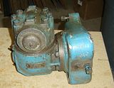
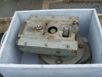
This past week I received a Brown & Sharpe No. 0 Universal Milling Attachment for my #2 "Light" mill. This is a double swivel milling attachment with a 2:1 step-up in the drive. It appears to be in pretty good shape, and the spindle & gears turn nicely. I haven't mounted it yet.
I also got a spare arbor support, and even the attachment crane to swing the milling attchment into place.
Some pictures: (All are clickable thumbnails)
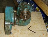
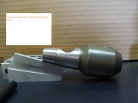
The hex key is used to turn a cam inside the spindle for tool retention. It looks just like a big camlock as found on the D1- series of lathe spindles.
The reason for retaining the tool in that fashion is easy to see from this end. There's no drawbar, and no easy way for B&S to have provided one.
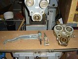
The attachment crane & roller clevis for swinging it into place. There's a pad on the right side of machine column to store the attachment. I will have to find a new place to mount the DRO counter, as I built a little swivel that uses the attachment crane's mount. My mill's original arbor support is mounted and the new one is on the table. It's a little hammered though it should work OK. The arbor supports are aluminum castings on this machine, by the way.
I hear you asking, "Aaron that's great, but what about the driver that fits into the spindle to power the silly thing?" Well, I was worried about that too, after reading the stories of the K&T attachments missing the critial driver, and the troubles with determining exactly the helical gear specs to replace it.
Turns out, B&S had a different idea. There is no driver that gets put in the spindle. Instead, there's a pair of straight cut spur gears inside the attachment, facing the machine's column. One of these gears accepts the spindle drive keys, which provides the drive to the attachment.
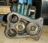
The driven gear is clearly smaller, though not half as big as would be needed to acheive the 2:1 increase at this stage. Presumably the bevel gears inside the swivels add to the ratio as well. The stated top speed of the attachment is 2700 RPM output, equating to 1350 RPM in. I don't recall the spindle speeds of the machine exactly though I believe 1350 is about 1 gear down from the top speed of 1500 RPM. This would give 15 possible speeds, top gear on the machine being above the rated output speed.
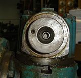
Looking into the spindle. The cam lock can be seen at the top, in the unlocked position. In the "neck" of the NMTB 30 taper is a spring, presumably to push the tool out when the cam lock is released.
The B&S #2 manual that I have, thanks to Jonny V, states that the spindle has a No. 30 taper and a Browne & Sharpe Cam Lock Construction (that's really what the manual says). A #9 B&S taper was optional, and clearly not what I have. I've never seen a Brown & Sharpe Cam Lock retaining system tool before, and I received no spindle tooling whatsoever. I have been unable to find any reference or drawings of what the cam lock arrangement on the tools should look like.
Any input here would be appreciated, if someone has a drawing of the tooling or even an actual tool, please let me know!
I seem to recall that some South Bend mills used a cam lock retaining system as well. I believe I have seen pictures of this, and I recall that it uses two locking devices which are positioned differently. I looked around the South Bend forum quickly but did not find the pictures I was looking for.
I plan to clean this up, probably involving disassembly to clean out the old grease & reservice the bearings and gears. I'll try to take pictures of this, when I get to working on it, and update this thread.
Now I just need to find a slotter, and a powered rotary table for the machine. I expect the rack cutting attachment may be scarcer than the proverbial hen's teeth, though!
Thanks for taking time to check in.
--
Aaron
I also got a spare arbor support, and even the attachment crane to swing the milling attchment into place.
Some pictures: (All are clickable thumbnails)

The hex key is used to turn a cam inside the spindle for tool retention. It looks just like a big camlock as found on the D1- series of lathe spindles.

The reason for retaining the tool in that fashion is easy to see from this end. There's no drawbar, and no easy way for B&S to have provided one.

The attachment crane & roller clevis for swinging it into place. There's a pad on the right side of machine column to store the attachment. I will have to find a new place to mount the DRO counter, as I built a little swivel that uses the attachment crane's mount. My mill's original arbor support is mounted and the new one is on the table. It's a little hammered though it should work OK. The arbor supports are aluminum castings on this machine, by the way.
I hear you asking, "Aaron that's great, but what about the driver that fits into the spindle to power the silly thing?" Well, I was worried about that too, after reading the stories of the K&T attachments missing the critial driver, and the troubles with determining exactly the helical gear specs to replace it.
Turns out, B&S had a different idea. There is no driver that gets put in the spindle. Instead, there's a pair of straight cut spur gears inside the attachment, facing the machine's column. One of these gears accepts the spindle drive keys, which provides the drive to the attachment.

The driven gear is clearly smaller, though not half as big as would be needed to acheive the 2:1 increase at this stage. Presumably the bevel gears inside the swivels add to the ratio as well. The stated top speed of the attachment is 2700 RPM output, equating to 1350 RPM in. I don't recall the spindle speeds of the machine exactly though I believe 1350 is about 1 gear down from the top speed of 1500 RPM. This would give 15 possible speeds, top gear on the machine being above the rated output speed.

Looking into the spindle. The cam lock can be seen at the top, in the unlocked position. In the "neck" of the NMTB 30 taper is a spring, presumably to push the tool out when the cam lock is released.
The B&S #2 manual that I have, thanks to Jonny V, states that the spindle has a No. 30 taper and a Browne & Sharpe Cam Lock Construction (that's really what the manual says). A #9 B&S taper was optional, and clearly not what I have. I've never seen a Brown & Sharpe Cam Lock retaining system tool before, and I received no spindle tooling whatsoever. I have been unable to find any reference or drawings of what the cam lock arrangement on the tools should look like.
Any input here would be appreciated, if someone has a drawing of the tooling or even an actual tool, please let me know!
I seem to recall that some South Bend mills used a cam lock retaining system as well. I believe I have seen pictures of this, and I recall that it uses two locking devices which are positioned differently. I looked around the South Bend forum quickly but did not find the pictures I was looking for.
I plan to clean this up, probably involving disassembly to clean out the old grease & reservice the bearings and gears. I'll try to take pictures of this, when I get to working on it, and update this thread.
Now I just need to find a slotter, and a powered rotary table for the machine. I expect the rack cutting attachment may be scarcer than the proverbial hen's teeth, though!
Thanks for taking time to check in.
--
Aaron


") . I just need some ER20 collets for test fit purposes. I may also try to make some regular CAT30 or NMTB30 into the B&S quick change 30, as suggested by svs. We'll see how it goes.
. I just need some ER20 collets for test fit purposes. I may also try to make some regular CAT30 or NMTB30 into the B&S quick change 30, as suggested by svs. We'll see how it goes.


 and had built up a number of misshaped blobs on the outside at the very end of the spindle. The table shows some circular scuff marks below its back edge, too. Now I know how they got there.