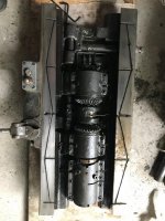
I have a VN22LU which looks fairly similar to the VN26, and I took the table off recently.
First step was removing the screw assembly. I removed the right side screw assembly but leaving the bracket on the table, since the left hand side is more complicated and has a screwed on nut, etc. That took a bit of doing getting that apart, but nothing major. The parts diagram is reasonably clear. The trick is to get the dial off, which reveals a setscrew-retained castle-nut which can slide off the shaft (keyed to the shaft IIRC).
Then I removed the screws holding the left hand side bracket to the table, and wound the screw out, tapping a bit to release from the pins. Winding the screw all the way out through the nut under the table (carefully, to avoid putting any strain on the parts). In this way, the table ends up ready to move.
Now remove the gib (loosening the gib lock screw).
The table is now resting on the flats. It should be able to move forward a bit into the space
where the gib was. The best way to take it off by far is an engine hoist, I put 1/2" eye hooks into T-slot t-nuts and the table is easy to manipulate. Watch out for any stops on the front of the table that would make contact with the left/right feed control handle assembly... and if you're sliding it off, be prepared for the weight of course, and perhaps lift it up a bit first, and squirt oil onto the mating surfaces...
If you're not using a hoist of some sort, perhaps leave the gib in (but loose) to minimize the risk of the table getting out of control as you push it toward one end. You can of course cantilever it onto a sturdy bench/table etc., and then lower the knee so the weight is mostly on the table. But be warned the table on the VL22L must be 300+lbs, yours must be similar?
I found my oil lines were mostly plugged up, with little to no lubrication to anything. Replaced all the oilers with new Bijur parts. While I was in there, I removed the caps various feed assemblies to clean it out. I found the oil line setup for the various power feed pieces not very good (4 legs of copper tube soldered to another piece) with leaks in some of the solder joints. So I'm replacing that with another Bijur manifold, individual oil meters for each, and "home run" tubing.
A "before" picture of the mess once the table was removed (and the saddle removed from the machine).


