stoneaxe
Stainless
- Joined
- Mar 2, 2010
- Location
- pacific northwest
Dr. Van Normanstein reporting from the lab-
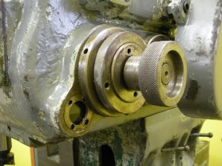
The gearbox oil level viewport is leaking and I want to fix it. - but the threaded retainer is trapped under another large threaded ring-
There is the shaft, a collar it goes through, and what look like two adjustment or lock rings on the collar, one of which traps the oil port retainer. It looks like there MIGHT be clearance to loosen the biggest ring, and get the oil port ring out from under?
I would sure like some advice here, or a drawing- my drawing for this is not the clearest of drawings-and does not show the shaft /bearing lock rings. I am a bit reluctant to dive in willy-nilly , these lock rings and collar look like they adjust bearing pre load on the shaft.
Pus I am sure that one of these parts is the lock ring holding the bearing the entire universe spins on, and if I screw up that one we are all in the deep doo doo!
Thank you!
 )
)