Hobby Shop
Stainless
- Joined
- Mar 20, 2014
- Location
- Michigan
Hi guys.
I'm missing all the worms & worm gears for my K&T 2CHL.
The ratios are. 1:96, 1:24 & 1:3.
Ramsay1 measured one gear for me and now I'm trying to figure out everything else.
I measured the center distance between the worm gears the best I could. I used gauge blocks between the 2 shafts and got 1.496 (each shaft is 1.312). Center is 2.808". I must be doing something wrong because using his measurements, I'm coming up with a different center dimension .
Center = 0.5(d+D)
[2.6860"]
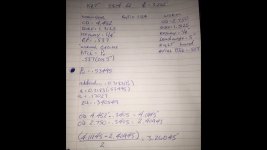
OD of worm gear is 3.9" with 24 Teeth
DP---- 26/3.9 = 6.66666
CP---- 3.1415/6.6666 = .4712
PD----24/6.66666=3.6
I'm also trying to find the lead of the gear but every formula I'm looking at in the machinery's handbook has the helix in it....Is there a way to solve for the helix angle with the info I have?
Worm, OD is 2.215"
8 teeth
Dp = 4.5146
CP = .6958
PD = 1.7720
I've got lots of books and I'm trying to learn as much as I can but gears are new to me.
Any and all help is always appreciated.
Andy
I'm missing all the worms & worm gears for my K&T 2CHL.
The ratios are. 1:96, 1:24 & 1:3.
Ramsay1 measured one gear for me and now I'm trying to figure out everything else.
I measured the center distance between the worm gears the best I could. I used gauge blocks between the 2 shafts and got 1.496 (each shaft is 1.312). Center is 2.808". I must be doing something wrong because using his measurements, I'm coming up with a different center dimension .
Center = 0.5(d+D)
[2.6860"]
OD of worm gear is 3.9" with 24 Teeth
DP---- 26/3.9 = 6.66666
CP---- 3.1415/6.6666 = .4712
PD----24/6.66666=3.6
I'm also trying to find the lead of the gear but every formula I'm looking at in the machinery's handbook has the helix in it....Is there a way to solve for the helix angle with the info I have?
Worm, OD is 2.215"
8 teeth
Dp = 4.5146
CP = .6958
PD = 1.7720
I've got lots of books and I'm trying to learn as much as I can but gears are new to me.
Any and all help is always appreciated.
Andy


")