I located the valve, but it is not the type I am used to. It has small "buttons" on each end. I pressed on both ends and they both depressed. When I restarted the machine, the tool pot moved up. However, I still have an ATC alarm and I can't do a tool change. I disconnected the solenoid, shut the machine off and restarted it, but the LEDs do not light up and the alarm persists. I really think I need to defer to a Kitamura tech.
View attachment 245288
Hello Fadal Error,
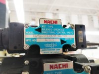
What LEDs are you referring to, the LED on a proximity switch, or the LED on the Solenoid Valve? If the latter, these are not used as inputs to the PLC to pass the position status of various components that are actuated by the hydraulic system. The LEDs on the Solenoid Valve simply show which Solenoid is energized. For example, lets say that a part of the Tool Change mechanism is immovably jammed and power is applied to one side of the valve. In this situation the spool in the valve will be moved by the Solenoid, but because the component being controlled by the valve is jammed, no confirmation of completion of movement of the component will be received by the PLC, as the proximity switch at the component has not been made.
I would be finding and confirming the status of all proximity switches associated with the tool change; staring with the tool pot if you think this component is the cause of the Tool Change not working. The Input address for the various proximity switches will be listed in a hard copy of the Ladder (there will be a list of I/O and a description of the use of each), and there will be (should be) an identification label on the actual wire from the proximity switch.
The PLC interface by Kitamura are normally quite good, but their recovery system for Tool Change errors have been not so good on some models. When sorting an out of kilter tool change, I normally disconnect all of the solenoid (they are normally in one area) power supply plugs, find a plug that has power to it (determined by a multi-meter) and use that plug to drive the various components back to their ready position. This plug may lose power as the PLC reads the proximity switches changing state. If this happens, find another with power and continue. This should then have ALL the proximity switches associated with the Tool Change Ready position ALL in the correct state.
By cycling the power to the machine, the PLC should see ALL of the inputs from the Tool Change in the Ready Position and direct power to the correct ends of each Solenoid (virtually resetting the PLC). Accordingly, when the power is off, and all the components of the Tool Change in the correct Ready Position, all of the power leads to the Solenoids can be reconnected.
If after completing the above procedure, the Tool Changer will still not work, then its likely that a proximity switch signalling the position of the various components of the Tool Changer has failed, or is out of position. This should be able to be confirmed by a LED on each of the proximity switches, or definitely by viewing the status of the switch via its address in the Diagnostic Parameters.
Regards,
Bill