Hi Guys,
I need advice with one of our parts. Attached 2# drawings.
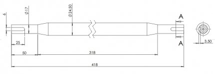
One of the actual Shaft(6x25-Plain) and another one tilted arrangement.
I need to cut (in single setup) 2# keyways in a shaft which measures 418mm in length. Straightness of both these keyways is very crucial. Now, my actual X-axis stroke of the machine is 400mm.
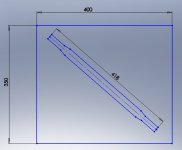
I'll be holding this in a V-block. I am thinking to "tilt" the V-block to appropriate angle within stroke limits so that I can cut these both keyways in single setup. Refer Image-Tilted6x25.
I need ideas to:
1. Find the exact Y-axis centre of the shaft.
2. Determine Angle of tilt.
I am open to accomplish this in 2 setups; provided there is foolproof method to get both these keyways aligned within 0.03 mm w.r.t shaft centreline.
P.S. Currently I am not equipped with any probing; so using probes is out of question here.
I need advice with one of our parts. Attached 2# drawings.
One of the actual Shaft(6x25-Plain) and another one tilted arrangement.
I need to cut (in single setup) 2# keyways in a shaft which measures 418mm in length. Straightness of both these keyways is very crucial. Now, my actual X-axis stroke of the machine is 400mm.
I'll be holding this in a V-block. I am thinking to "tilt" the V-block to appropriate angle within stroke limits so that I can cut these both keyways in single setup. Refer Image-Tilted6x25.
I need ideas to:
1. Find the exact Y-axis centre of the shaft.
2. Determine Angle of tilt.
I am open to accomplish this in 2 setups; provided there is foolproof method to get both these keyways aligned within 0.03 mm w.r.t shaft centreline.
P.S. Currently I am not equipped with any probing; so using probes is out of question here.