What's new
What's new

A36 steel milling help

bastarddsm

Aluminum
Joined
Feb 18, 2014
Location
Southern Illinois University
I'm sure this is pretty trivial to many of you, but, I have a few parts to make out of what I assume is A36 structural steel. These are hitch parts for tractor pulling. The customer has supplied a 1.5"x8"x36" bar of hot rolled steel, that I assume is A36, and I need to make 4 of these out of it. I'm just starting with this stuff, and have a pretty good handle on running aluminum but not steel.

I have a Tree VMC 1060,(16klbs, 40 taper, box way, 20hp, 40x24 for those who don't know) and it's on a 15hp rpc, so I don't have all the spindle power available. I have 2 china 6" vices. I don't have much budget for tooling at this time. I bought a couple 3/4" 6 flute carbide endmills, and a few 1/2" ones as well. I

What's the best plan of attack? Minimal tooling expense is favored over quickness, I don't have a lot of other work to do on the machine right now. I also have tons of other stuff to do while this is cutting, so it needs to not need babysat.

My plan was saw cut the bar into blocks just a bit over 8". Put the jaws on the outside of the vice, and set them on the vice, grabbing the saw cuts and square up the as rolled sides so I have something to locate off. After that turn them 90* and square up the saw cut on one side. Then profile it down to a little over half depth. Probably use a drill to start the hole, then endmill to carve the pocket down to a little over half depth. Flip it over, then start the profile and pocket routine over. I planned on making a negative of the part I could bolt on a 90* angle plate to hold it to drill and then thread mill the bolt holes.

I have no idea on depth of cut and speed. Only steel I've cut has been on a bridgeport, and it was slow and suck, so I have no idea what to do on a real machine. I planned on running the 3/4 6 flute since it's the biggest thing I have that will fit in the corners and and it has the right corner radius. How deep and how fast should I be running it? Should I be using a different tool? Should I use coolant, it has flood and has QC 215C in the machine.
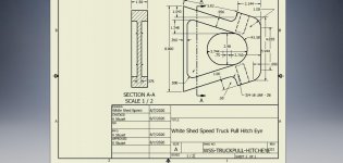
WSS-TRUCKPULL-HITCHEYE.jpg
 
Much of this depends on tooling, of course.
First, because of power limitations, you can't go too aggressive and you already know this. When I cut A36 HRS, I like to "get under" the outside skin of the part. I do this so the cutters don't take a beating from the scale. So your first cut should be deep enough to do this.

I like the idea of squaring up the part first and it's usually what I do. Same for the pilot drill before milling.
For Feed/Speed, check machinist's handbook! If you don't have one, check the library, they may have a copy, or Ebay/Amazon.
 
All that design work, and then they hand you some "unknown" crap steel ?

Looks like it should have been made from 4140-ht.

UGH.
 
Looks like it should have been made from 4140-ht.

It might be! OP says he doesn't know what material he was given.

With your power limitations, I would recommend HSM toolpaths if your CAM and control allow, and work the radial engagement up from, say, 5-6%, until you start having power issues.

Regards.

Mike
 
Personally I would rough it out in 2 levels with a 3/8" or 1/2" 6 flute leaving a .010" step so I didn't have to relieve the shank of the tool. Then I would come in and finish it with a longer tool. I would use a 3/4" since I have a bunch of long ones laying around but if I had buy one I would likely use a long 1/2" since they are a lot cheaper. I almost always run endmills dry in steel.
 
I second the idea of using 1/2" endmills - in fact, if you can send the 3/4" ones back and get more 1/2". Not as fast perhaps, but much less painful when you break one, and you will...

Make your pilot hole at least 3/4", or 1/2" drill, then spiral with a 1/2" endmill to make a 1" clearance hole. Cut to a little over half the thickness of the steel, using perhaps .04 - .05" width of cut, relatively high rpm and feed. Air blast if possible to clear chips, but if the machine is not enclosed beware of chips flying everywhere.

Be careful with using outside mounted jaws to hold the work, the grip capacity isn't ideal due to the thin "washer" of steel jaw bolting surface taking all the load, and the low engagement height. I would square the stock before any major cuts to ensure best possible holding.

Maybe better to strap clamp the part down to the vise at either end if possible to "belt and suspender" the plate. Don't let it tilt if you try this.

You do wear eye protection, right?
 
May as well make it out of old Toyota bumpers ... did you notice the two 3/4" holes right across the highest stress area ? What's that for, "break on dotted line" ?

Just saw the drawing - agree with EG, unless I totally don't understand the loading I don't like how thin a section it becomes at the bottom of the two tapped holes.

If my redneck math is correct it should have the same theoretical strength where the holes are as it does just to the left of them where the cross section thins out. Yes the threads create stress risers but a couple quick numbers in my head say this should have a yield point of arouns 100,000 lbs if made from A36 and about twice that for failure. I can't imagine a pulling tractor being that much.
 
If my redneck math is correct it should have the same theoretical strength where the holes are as it does just to the left of them where the cross section thins out. Yes the threads create stress risers but a couple quick numbers in my head say this should have a yield point of arouns 100,000 lbs if made from A36 and about twice that for failure. I can't imagine a pulling tractor being that much.

Wait - you're a redneck but you can do math? What sort of strange beast are you??

[big :D]

Yeah, it may be fine, but I'd still rather see more metal there. It's the impulse loading that worries me, from what I've seen of tractor pulls there's sometimes a lot of shock, not always a smooth takeup of the loads. I'd cut the depth of the holes by ~.5" if I had my way.

I'm guessing those are for safety chains? Given the angle, I hope the chains can't snap the eyebolts or whatever off - a straight pull would be a lot better...

It a combination of the Tide Pods and the fact I grew up in New England :eek:

It's been years since I've played around with any pulling stuff but IIRC the sanctioning body has "specs" for the attachment point?
 
Another thing - if the plate is getting welded using that left side face, the loads are going to be concentrated along the sides, the .35" section isn't going to add much. I'd beef the .35" to .75" to get a better load distribution. Better still, make it a parabolic transition.

Just my 2 centavos.
 
I'm guessing those are for safety chains? Given the angle, I hope the chains can't snap the eyebolts or whatever off - a straight pull would be a lot better...

I don't recall seeing any safety chains, just a wire cable for the kill switch.
 
Much of this depends on tooling, of course.
First, because of power limitations, you can't go too aggressive and you already know this. When I cut A36 HRS, I like to "get under" the outside skin of the part. I do this so the cutters don't take a beating from the scale. So your first cut should be deep enough to do this.

I like the idea of squaring up the part first and it's usually what I do. Same for the pilot drill before milling.
For Feed/Speed, check machinist's handbook! If you don't have one, check the library, they may have a copy, or Ebay/Amazon.

Thank you for the helpful response

All that design work, and then they hand you some "unknown" crap steel ?

Looks like it should have been made from 4140-ht.

UGH.
UGH, answering questions that were not asked. It's a weldment, so I should be sending material needing pre and post heat home with a farmer that's gonna glue this on with a buzzbox and 6010. And it should be 4140ht so it's 10x stronger than it needs to be, and just the billet costs what the part sells for? Good one.

It might be! OP says he doesn't know what material he was given.

With your power limitations, I would recommend HSM toolpaths if your CAM and control allow, and work the radial engagement up from, say, 5-6%, until you start having power issues.

Regards.

Mike
It's not 4140. I just don't know if it's like 1018 or A36


Personally I would rough it out in 2 levels with a 3/8" or 1/2" 6 flute leaving a .010" step so I didn't have to relieve the shank of the tool. Then I would come in and finish it with a longer tool. I would use a 3/4" since I have a bunch of long ones laying around but if I had buy one I would likely use a long 1/2" since they are a lot cheaper. I almost always run endmills dry in steel.

May as well make it out of old Toyota bumpers ... did you notice the two 3/4" holes right across the highest stress area ? What's that for, "break on dotted line" ?
It's very possible it is old toyota bumpers. It's also possible that I'm much better at making sure it DOESN'T have a break on dotted line, than you are at staying on topic.

I second the idea of using 1/2" endmills - in fact, if you can send the 3/4" ones back and get more 1/2". Not as fast perhaps, but much less painful when you break one, and you will...

Make your pilot hole at least 3/4", or 1/2" drill, then spiral with a 1/2" endmill to make a 1" clearance hole. Cut to a little over half the thickness of the steel, using perhaps .04 - .05" width of cut, relatively high rpm and feed. Air blast if possible to clear chips, but if the machine is not enclosed beware of chips flying everywhere.

Be careful with using outside mounted jaws to hold the work, the grip capacity isn't ideal due to the thin "washer" of steel jaw bolting surface taking all the load, and the low engagement height. I would square the stock before any major cuts to ensure best possible holding.

Maybe better to strap clamp the part down to the vise at either end if possible to "belt and suspender" the plate. Don't let it tilt if you try this.

You do wear eye protection, right?

Thanks for the detailed reply. It is enclosed. I'll have to rig up an airblast. I did one on my dads little EMCO F1CNC. Was just a piece of 3/16" brake line in a p clamp on a magnet stuck to the side of the head. Some hose and a regulator set just high enough to blow aluminum chips away, but not high enough to make the compressor run constant. Is that the idea here?

I have 1 issue with that. I don't have good power here yet, and when I was running aluminum (8000rpm) if my 5hp compressor is running when the spindle starts it usually faults the drive from low voltage. I have to nurse it up to 8000 in steps to keep it happy on my small vfd and shit power. Even taking 4 steps it sits at 200% spindle load for a bit spooling up. Anyway, I'll try it. What's my alternatives if this becomes a problem.

Can you show me an example of strap clamp? I think I have an idea but not sure.

If my redneck math is correct it should have the same theoretical strength where the holes are as it does just to the left of them where the cross section thins out. Yes the threads create stress risers but a couple quick numbers in my head say this should have a yield point of around 100,000 lbs if made from A36 and about twice that for failure. I can't imagine a pulling tractor being that much.

Thanks for trying to bring some sanity to this. I didn't run FEA on this, but there are 4 .750x2 sections loaded in tension, that's 6 sqin of 60ksi tensile material. They shouldn't ever see anywhere near yield strength, they would likely just rip the 1/8" wall sq tube hitch mounts off the stockish gm truck frame. Anyway this in a diesel truck about 1300hp, and I think like 2000ft*lbs tq. I tuned the damn thing and I can't remember the exact numbers. The other one is 2000 and 2800 or so, and uses the same design. They run about 10-14:1 overall gear reduction, and 35" tires. Assuming 100% traction they don't make 20klbs of pulling force. Double it for some dynamic action, and we still have A LOT of room to spare. It's a simple design, that works well, and is guilty of nothing but not being very well optimized and having too much meat in some areas. It's very light and strong compared to what many others fabricate. We had one guy that made one similar to this out of aluminum weldments. It worked for a while.


To clarify for everyone else, it gets 2 pieces of 1/2x2 flat welded on the sides, and a tube at the other end to space them out and become a "hinge" Ends up in a triangle shape. The bolt holes are for the hitch height adjuster mounts. This is a proven design used on many many trucks. They don't fail. The normal supplier is out of stock and to busy to get them done soon, so the local ringleader asked me to get make them for the 4 trucks getting built currently. All I did was turn a rough sketch into a drawing so fusion will program it for me.

So can we get back to helping figure out how best to do this and make the most money. I get $175/ea for machining them, If I burn up a handful of $50 endmills, kinda kills the profit.
 
Another thing - if the plate is getting welded using that left side face, the loads are going to be concentrated along the sides, the .35" section isn't going to add much. I'd beef the .35" to .75" to get a better load distribution. Better still, make it a parabolic transition.

Just my 2 centavos.

I don't think there is much stress in the webs at all. It's all in the thick part. The original one is a weldment of a flame(plasma?) cut thick piece and the thinner webs. They were both thinner than my drawing. I added material there in the drawing to make less material to remove and thickened that front web so I can clamp on it. It's probably not strong enough for clamping, but I thought I'd try. It's like 2x thickness of original.
 
Ohhhh...these are for truck pulls, and probably "stock" (seeing the 2" receiver hitch dim.)

I thought it was on the sled.
 
I have 1 issue with that. I don't have good power here yet, and when I was running aluminum (8000rpm) if my 5hp compressor is running when the spindle starts it usually faults the drive from low voltage. I have to nurse it up to 8000 in steps to keep it happy on my small vfd and shit power. Even taking 4 steps it sits at 200% spindle load for a bit spooling up. Anyway, I'll try it. What's my alternatives if this becomes a problem.

You should be able to go into the parameters either on the control or the drive itself and adjust the accel/deccel rate to drastically reduce your inrush current and eliminate "stepping" the spindle up.
 
Thanks for the detailed reply. It is enclosed. I'll have to rig up an airblast. I did one on my dads little EMCO F1CNC. Was just a piece of 3/16" brake line in a p clamp on a magnet stuck to the side of the head. Some hose and a regulator set just high enough to blow aluminum chips away, but not high enough to make the compressor run constant. Is that the idea here?

Yes, basically just using air to sweep away chips from the cut zone. Doesn't have to be super-powerful, just enough to ensure there's not a bunch of chips piling up over the cutter - recutting chips is a good way to damage carbide endmills and the surface finish of the part.


Can you show me an example of strap clamp? I think I have an idea but not sure.

Something like this: https://www.amazon.com/PENSON-CO-Clamping-Upgraded-Bridgeport/dp/B01CZZGH5Y?ref_=fsclp_pl_dp_11

I'm thinking on strap on either end of the part just outside the cut area, so that if the part tries to rise up out of the vise the strap restrains it.


So can we get back to helping figure out how best to do this and make the most money. I get $175/ea for machining them, If I burn up a handful of $50 endmills, kinda kills the profit.

Yeah, stick with 1/2" endmills.
 
You should be able to go into the parameters either on the control or the drive itself and adjust the accel/deccel rate to drastically reduce your inrush current and eliminate "stepping" the spindle up.

I've been thinking about doing that, just have not had time to tinker yet. I literally just made my first parts on it a couple weeks go. The compressor issue never happened till the last batch. I'm slowly learning the quirks of my setup.

Who is the dynapath/yaskawa guru that can help with that? I've bugged ZPS and dynapath a lot while getting this going. I think they need a break from me.


Back
Top