What's new
What's new

Anilam 5000M Knee Mill - Repair or upgrade\refit

1664

Plastic
Joined
Jul 18, 2018
Good afternoon everyone.

My 10-year-old knee-mill, it came from a college earlier this year so is little used and in very good condition, has developed an E-stop fault in the Anilam 5000M control. Initially, the 24v power supply went hi and ran 44v as the control signal, replaced it with a new one and I now have the correct voltage across the system. I have tracked the fault it down to the console and beyond that my skills aren't good enough to gain further insight into the fault.

I have asked a company in the USA about repair and I have been told I will need to send the control to them, I live in the UK, and it could cost $1000-3000 plus about $400 in postage/courier costs. If I deem it too expensive to repair it will still set me back $750-1250 plus postage.

As much as I like the control, I find it fairly intuitive and it has worked very well with Fusion 360 posts, it could well be far too expensive for me as a one-man band to have repaired, especially if it needs further work in the near future.

I thought to upgrade it to the Centroid Oak board and keep the Glentek SMA 9115-000-1-121B Amps and Acu-Rite HJ130-A8-44S AC brushless servos and add an inverter into the mix to give me spindle control. This still isn’t going to be particularly cheap, but it will at least give me an up to date controller that has a period of warranty. These items will work with the Oak without the need to fiddle with the servos.

Changing out the servos and drives to newer items is cost prohibitive.

Are there any other choices for controls for AC amps and servos and has anyone done this refit or similar - your advice and superior knowledge would be most welcome.

I do want to stay away from Linux, I don’t have the competencies to use it. I use Mach 4 on a lathe, but without the commercial variant it is lacking in some respects and I have no idea if there is a system to integrate it to run an AC system nor probably want to.

Many thanks.
 
has developed an E-stop fault in the Anilam 5000M control

Do you mean to say that it's stuck in e-stop?

The older Anilam controls (Crusader series) had a relay inside the control box that served as the main e-stop relay. I have no first hand experience of the newer anilams like yours, but they are likely the same. The entire e-stop string in the machine terminated at this relay, so if anything on the machine wasn't closed (hard limit switches, oil pump, interlocks, external e-stops, whatever) the relay would be open and the control would be in e-stop. Accordingly, if the relay fails, or if there is a wiring fault between the relay and the control, the control will be stuck in e-stop.

It's also possible that if 44v reached whichever board the relay is connected to, that you may have fried an optocoupler on the input.

This is all assuming that you've actually rung out the e-stop string already.
 
Hi, it does say on the control that it is an e-stop.

As far as I can see the X, Y, Z limit string is working ok and nothing else appears to be in that string.

Had a check of the K1 relay, it appears to function well, but it seems it's not getting power on startup. Tried chasing the various connections back and keep ending back at the DSP board.

DSP board doesn't appear to output a servo enable signal and as you say that may be caused by an optocoupler failure or similar. Unfortunately, I don't have any schematics of the DSP board.

Plus I can't seem to see the reset signal, the reset servo button functions on the control and inputs 5v to the DSP but little else appears to happen. And I'm unsure what is meant to be seen first.

My electronic skills are limited.

simlified schematic.jpg
 
The schematic you attached is too small to read. If possible use an external image host like imgur.

The way the relay normally works is the e-stop string is terminated across the coil, and the control connected to the N/O contacts. If the e-stop string is closed the coil should be powered. Did you ring out the string to make sure it's closed? I'm skeptical that the limits are the only things in the string. Slide lube pump is usually in there, and any other e-stop button anywhere else on the machine, although it's possible that your newer anilam is smarter about the oil pump and has a seperate input for that...

You say the relay functions, how did you test it?
 
use a simple volt and ohm meter.
Put it to ohm, Turn off the power for the machine and let it rest for 10 mins.

The E-stop circuit will if built by someone sane, have at least two 'circuits' one

Take out the relay and measure that there is impedance through the coil between A1 and A2, meaning the coil is not burned.
Im not sure on the exact relay in there, but they can often be activated by a button on the relay, measure the reistance (ohm) trhough the contact sets (ex: 11,12,14 etc) and check the contact sets works in both directions correctly.
the general issues with relays are either burned coils or burnt contacts on the switch points.
On a relay like that that satys on constantly they tend to induce heat when they get old and at some point sooner or later they fail.
A normal non solid state relay has a normal expected life of 50-100 000 operatiosn usually, under normal circumstance about 20 degrees celcius, and they dont tend to improve in quality over the years.
And i imagine the contact sets should be okay, since it would normally just be used to send the controllers ref voltage back to a signal input.

The schematic you linked is just too small in format to be readable as mentioned so cant help you from that.


Check your limit switches the same way, ohm meter on each side of the contact points and verify they work, any safe stop, limit switch etc. Shoudl be NC contacts by nature, so if they fail the machine will malfnction on purpose for obvious safety reasons, just as it has now and give you a e-stop error.

If you verify that all works, power up your machine, be careful with the measuring pins not to shortcircuit things on boards etc by slipping them,


Set your instrument to voltage reading, Start by checking per the schematic that you have the negative supply to normally the A2, relay coil coil with the machine on, measure from a2 to the boards reference +.

Then find the wire output from the conroller going to the limit switches etc in the e-stop fnction per the schematic.
measure your voltage output between that wire and your reference on the board, normally the boards -. look it up on the schematic and verify you send volatage out to the e-stop circuit.

From there check your voltage from reference again and back into the controller from the e-stop crcuit with everything in place, if the relay is drawn and you have the corect volatge back to the input something on the boards/controller is the issue. If not its a issue with something in your E-stop circuit simple as that.

If so contnue voltage measurement from reference to every contact point and check where you loose your voltage that should be going to your relay coil.

Can always do this first as it will give you a definite answer on where you have a issue and might be the faster option. just exercise care when you use the ohm part of the instrument on something with power on, it has some potential for destruction.

A schematic that can be zoomed in and read woudl make it a whole lot eeasier to help, your pic dont have the resolution to be read when zoomed in.


k
 
Hi, thanks for your time and especially patience.

Take out the relay and measure that there is impedance through the coil between A1 and A2, meaning the coil is not burned.
I’m not sure on the exact relay in there, but they can often be activated by a button on the relay, measure the resistance (ohm) through the contact sets (ex: 11,12,14 etc) and check the contact sets works in both directions correctly.


There is a resistance of 640 ohms across the coil. There is a data sheet for K1 and the model is MY 24VDC (S) and is at the link.

I did take K2 out of the cabinet and attached a bulb to one side of it and put a 9v battery across the other side and the bulb lit, so K2 is working.

the general issues with relays are either burned coils or burnt contacts on the switch points.
On a relay like that that stays on constantly they tend to induce heat when they get old and at some point sooner or later they fail.
A normal non solid state relay has a normal expected life of 50-100 000 operations usually, under normal circumstance about 20 degrees Celsius, and they don’t tend to improve in quality over the years.
And i imagine the contact sets should be okay, since it would normally just be used to send the controllers ref voltage back to a signal input.


Relay provides continuity across the contacts as it should when active or inactive.

The schematic you linked is just too small in format to be readable as mentioned so can’t help you from that.

The link goes to a number of documents and page 6 of the 3000M wiring diagram is the one I’m working to.

https://1drv.ms/f/s!AhDYD0_HVekngqlWYZUZ0tQR1DDKtQ

Check your limit switches the same way, ohm meter on each side of the contact points and verify they work, any safe stop, limit switch etc. Should be NC contacts by nature, so if they fail the machine will malfunction on purpose for obvious safety reasons, just as it has now and give you a e-stop error.

I have placed a link in the X and Y axis string to bypass those limits and checked the Z, all OK. See page 88 and 89 in the PN 70000506H Anilam OEM CNC Installation PDF at the link.

Page 90 there is no pin 4 or 10 on the connector P15.

Set your instrument to voltage reading, Start by checking per the schematic that you have the negative supply to normally the A2, relay coil with the machine on, measure from a2 to the boards reference +.

Then find the wire output from the controller going to the limit switches etc in the e-stop function per the schematic.
measure your voltage output between that wire and your reference on the board, normally the boards -. look it up on the schematic and verify you send voltage out to the e-stop circuit.


No voltage is going to the limit string.

From there check your voltage from reference again and back into the controller from the e-stop circuit with everything in place, if the relay is drawn and you have the correct voltage back to the input something on the boards/controller is the issue. If not it’s an issue with something in your E-stop circuit simple as that.

I have 24v on the e-stop switch in the console

If so continue voltage measurement from reference to every contact point and check where you lose your voltage that should be going to your relay coil.

I can only think that there isn’t any signal getting to pin 5 or 8 on P15?

Unfortunately I have no actual wiring schematic of the boards, just the interconnecting wiring.

Many thanks for your help.
 
Is this 5000 an OEM or a kit style system?
A Kit style system uses a large umbilical cable between the console and the servo box. This cable uses a latch on the console to hold this large cable to the bottom right rear corner of the console.
Does yours 5000 use this? If you are not sure, please what is the Tag with the ANILAM name on it. I need all the information from this tag.
I work for HEIDENHAIN, they own the ANILAM brand name.
I can be reached at 716-661-1883 or work e-mail [email protected].

Jerry Bouvier Jr.
 

Attachments

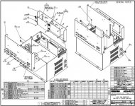
  • image006.jpg
    image006.jpg
    85.9 KB · Views: 137
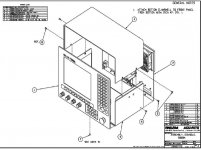
  • image001.jpg
    image001.jpg
    62.6 KB · Views: 202


Back
Top