What's new
What's new

Assistance with 2D programming this 3D part.

SigurdACVW

Aluminum
Joined
Aug 16, 2013
Location
IL
I've been on a Haas Minimill 2 and a 2D seat of Mastercam 2017 here at work for about a month. I have experience with Mastercam X5 and my Sharp 2-axis mill. I'm on my own for figuring out the programming of the Haas.

This is what I'm working on. It's a sprue bushing, part of an injection mold. I need to cut the angled walls (30 degrees included) and the .085" radius on the floor. The hole is already there. Ordinarily, I'd rough it out, then grab an 11/64 ballnose endmill to finish the radius and then make a 15 degree cutter on the Deckel and call it a day. Maybe put it all on one cutter. However, I'd like to try programming this time. I've been watching some videos on YouTube about the Swept 2D toolpath, but I can't seem to get it to work. It asks for the "across" contour, but never asks for the "along" contour, just "branch point reached". Would someone be willing to provide some guidance here? Thanks.
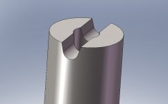
sprue bushing.jpg
 
try selecting the across and hit the + symbol not the check mark then select the along, and at this point you can then hit the check on the selection dialog box.

for this particular toolpath I don't think it prompts you.
 
If I was going to 3d that, I'd probably first add a surface, or remove the hole feature to make it a nice smooth U shape. Then I would probably just do a paralell toolpath for rough and finish and call it done. I assume this will be hand polished since it's for the runners/sprue and you don't want it to stick?
 
try selecting the across and hit the + symbol not the check mark then select the along, and at this point you can then hit the check on the selection dialog box.

for this particular toolpath I don't think it prompts you.

I tried that. Using the + key didn't seem to have any effect.

If I was going to 3d that, I'd probably first add a surface, or remove the hole feature to make it a nice smooth U shape. Then I would probably just do a paralell toolpath for rough and finish and call it done. I assume this will be hand polished since it's for the runners/sprue and you don't want it to stick?

This is going to show where I'm at with Mastercam, but I don't know how to create surfaces or plug holes. Sounds like that's where I need to start.

Also, it doesn't appear that Parallel toolpaths are available with my seat of MC (2D only). The guy I'm sharing the machine with has the 3D seat.
 
I'm with Mike on this one.

Although you have a seat of Mastercam 2D, there's still a number of 3D cutter paths you can use - I think with all the "surface high speed" you can do one surface at a crack. I believe there's a couple of legacy toolpaths you can program multiple surfaces with. Parallel being one and multisurface pocket being the other (pretty sure, please don't hold me to it).

Anyways, what'd I do is construct in the front plane and curve the edges of those angles and the radius slightly so they project slightly off of the part and in the same plane so they're flat. Then go into your surface menu and use "draft" and extend that new surface across your part to cover up that hole. Then grab whatever tool you want and have at it with a parallel cutter path.
 
This is going to show where I'm at with Mastercam, but I don't know how to create surfaces or plug holes. Sounds like that's where I need to start.

Also, it doesn't appear that Parallel toolpaths are available with my seat of MC (2D only). The guy I'm sharing the machine with has the 3D seat.

1. Make a new plane such that you are looking down the length of the surface
2. Project the (3D) edges of the surface to some Z value, making a new 2D projection of that 3D surface
3. Project a copy of that new 2D contour by the diameter of the cylinder
4. Create a new surface between those two new chains with "Loft"
5. Transform that new surface such that it is oriented at the correct Z
6. Flowline a 1/8" ball endmill along that new surface

If you send me a Zip2Go of your MCAM project I can make an example.

Regards.

Mike
 
I tried that. Using the + key didn't seem to have any effect.


This is going to show where I'm at with Mastercam, but I don't know how to create surfaces or plug holes. Sounds like that's where I need to start.

Also, it doesn't appear that Parallel toolpaths are available with my seat of MC (2D only). The guy I'm sharing the machine with has the 3D seat.

It might prompt you to select an intersecting point, Did it?. you should only to need to select 2 entities literally 2 straight lines is all you need. for swept 2D.
 
I'd just make a new level and use Surface-->From Solid followed by Surface-->Extend to make a drive surface with some extra run-on/run-off.
 
1. Make a new plane such that you are looking down the length of the surface
2. Project the (3D) edges of the surface to some Z value, making a new 2D projection of that 3D surface
3. Project a copy of that new 2D contour by the diameter of the cylinder
4. Create a new surface between those two new chains with "Loft"
5. Transform that new surface such that it is oriented at the correct Z
6. Flowline a 1/8" ball endmill along that new surface

If you send me a Zip2Go of your MCAM project I can make an example.

Regards.

Mike

It might prompt you to select an intersecting point, Did it?. you should only to need to select 2 entities literally 2 straight lines is all you need. for swept 2D.

The command says "define the across contour". From the chaining dialog box, I select a chain consisting of down the 15 deg wall, the radius, and the up the 15 degree wall. But, by the time I have clicked the first segment (down the wall) the command says "branch point reached". If I continue to click all three segments and then green checkmark, it's asking for the intersection of across and along, and I never got to define along.

If I try your method of down the 15deg wall, and then the line on the top of the part in the direction of the slot, it will ask for the intersection point. When I click the intersection point, I get an error message saying that "swept 2d toolpaths should only contain 3 contours."
 
1. Make a new plane such that you are looking down the length of the surface
2. Project the (3D) edges of the surface to some Z value, making a new 2D projection of that 3D surface
3. Project a copy of that new 2D contour by the diameter of the cylinder
4. Create a new surface between those two new chains with "Loft"
5. Transform that new surface such that it is oriented at the correct Z
6. Flowline a 1/8" ball endmill along that new surface

If you send me a Zip2Go of your MCAM project I can make an example.

Regards.

Mike

I have a Zip2Go made. Should I PM it to you?
 
The command says "define the across contour". From the chaining dialog box, I select a chain consisting of down the 15 deg wall, the radius, and the up the 15 degree wall. But, by the time I have clicked the first segment (down the wall) the command says "branch point reached". If I continue to click all three segments and then green checkmark, it's asking for the intersection of across and along, and I never got to define along.

If I try your method of down the 15deg wall, and then the line on the top of the part in the direction of the slot, it will ask for the intersection point. When I click the intersection point, I get an error message saying that "swept 2d toolpaths should only contain 3 contours."

are you using partial selection method?

select partial chain then the 15 degree downslope line and the the 15 degree upslope line. thats one chain then select the straight horizontal line thats line 2.

under chains you should only have 2 selected
 
are you using partial selection method?

select partial chain then the 15 degree downslope line and the the 15 degree upslope line. thats one chain then select the straight horizontal line thats line 2.

under chains you should only have 2 selected

I've tried that. It's not finding the partial chain.
 
I tried just that and finally got it to ask me for the "along" contour. Green checkmark, and it asks for the intersection point. Upon clicking the intersection point, the new error message I get is "The across contour does not lie in a defined view". That's true, right? It's a cylindrical part. Someone mentioned earlier about projecting it onto a plane that is offset from the part. Does that come into play now?
 
I analyzed the entities in question, and they are splines. They will not simplify either, even with a wide-open tolerance. Is that my issue?
 
I tried just that and finally got it to ask me for the "along" contour. Green checkmark, and it asks for the intersection point. Upon clicking the intersection point, the new error message I get is "The across contour does not lie in a defined view". That's true, right? It's a cylindrical part. Someone mentioned earlier about projecting it onto a plane that is offset from the part. Does that come into play now?

try it again but this time make sure your construction plane is set to right side or front. what's happening is you are trying to create it in a different plane

make sure front or right side have the "C" in yours planes window


Back
Top