What's new
What's new

Best way to dial in offsets for corner round tool?

KristianSilva

Aluminum
Joined
Nov 26, 2016
I'm using a Haas TM1P and basically want to know what is the best way to dial in the length and discuss offsets of either a corner radius mill or bullnose endmill when forming a radius on a part?

I ask because I am setting tools manually which isn't always the most accurate process and I want to produce an accurate size fully formed radius that DOESN'T gouge.

Thanks in advance!

blend them in to where you get full radius and no cutting into the material from the side or top of the tool. I like to put the tool on a comparator and see exactly what the distance from the tip of the tool to the radius in z then I check the distance from old of the tool to radius. Then you can look at your z depth in the program and adjust the tool up a few thou to see how close you get while adding say .012 for the y or x axis to back your tool off on the side. Then it is a matter of run - check-adjust - repeat until it is perfect.
 
Hi Kristian:
There are a few things you can do to improve your success.
The first and most important is to split up the offsets so you can manipulate them independently and sneak up onto the diameter offset first and the height offset second.
The way to do that is to program the path with G41 or G42 so you can manipulate the effective tip diameter with a wear offset in the control:
Program your path with the nominal tip diameter and add 0.005" of stock allowance to the nominal path but with G41 (or G42 if you want to conventional mill rather than climb mill).
Now run your cutter well above it's final height so only the tip cuts.
Changing the compensation value in the control, you can run around the path until the tip is cutting just a twitch deeper than you want, then back the comp value off to where it was "just right".
This allows you to get within tenths with perfect control.
Now you can do the same again with the Z level; setting the diameter offset so only the very edge of the biggest diameter of the cutter is cutting, and drop down in Z until again your cutter is cutting just too deep and then back off one increment.

Now you can simply re-set your diameter offset and you're good to go; that particular cutter is dialled in.
All of your test cuts will blend in because they were all done in the waste stock, so even the trials where you overshot a bit will clean up perfectly.
That's why you ran the cutter above the proper height for the first offset settings and at a bigger diameter for the second offset settings.

There are a few other things you can do too, to help achieve success.
If your need is primarily cosmetic and not geometric fidelity, you can modify the cutter slightly.
If you stone both ends of the radius on each flute just a twitch, the cutter will become less sensitive to precise positioning and will still make a good-looking radius.
This can be helpful if your top surface is not perfectly flat.
Similarly you can grind a tiny bevel at the corners of the cutter so long as you make its angle very shallow and blend it perfectly with the radius so it's accurately tangent to the rad.
You can also get a nicer cosmetic result if you play the cutter up a thou and out a thou compared to where it should be in a theoretically ideal world: your geometry will be incorrect but often it'll make no functional difference, however the work will look much nicer.

The best way, is to abandon the form cutter all together and learn to 3D surface those features instead of form cutting them.
When you must make time on the job, a form cutter is a lot faster, but when you must have the best looking outcome, surface milling them will give the nicer result by far.
I use 3D Contour or Flow or Scallop (I'm running HSMWorks) depending on the geometry and all do a much better looking job than a formcutter can ever hope to do, but they take a LONG time by comparison.

So that's it in a nutshell; try all the techniques out, see which one suits your job best and give 'er a go!

Cheers

Marcus
Implant Mechanix • Design & Innovation > HOME
Vancouver Wire EDM -- Wire EDM Machining
 
I like to put the tool on a comparator and see exactly what the distance from the tip of the tool to the radius in z

I'm gonna say- if someone has a Haas TM1P, they probably don't have a comparator sitting around to dial in their stuff to 0.0002"...

The way I do this is run test cuts on some scrap material. I take a 2"x2" cube, clean up the top, and do a little hexagon shape so I have 6 edges. Program the first edge by the book, evaluate, and dial in the Z height (I use stock to leave in HSM Works to do this) and cut the second edge. After that, I dial in diameter (again, using Stock to Leave). Just keep working your way around and by the time you get to Edge 6, you should be totally dialed in.

In HSM Works, you can save a CAM operation as a template, so I dial everything in using Stock to Leave for the fudging, and fire that saved template off when I program. This keeps it all easy to do and you aren't futzing with compensation in the control every time you want to use the tool (this is bozo prevention 101).

Once you get that tool dialed in, you should be good to go with the same numbers if it ever needs replacement. The Harvey radius cutters with the angled lead in/out are really the way to go.
 
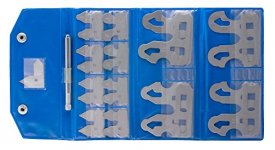
Depending on the part's shape, you might be able to use some sheet metal radius gauge feelers. The problem is they often have a large overhang which might prevent them from fitting on your workpiece, but they do make life easy :)

If all else fails you can always buy a set then trim off much of their excess shape.
 

Attachments

  • 51DX5aqVvmL.jpg
    51DX5aqVvmL.jpg
    32.6 KB · Views: 88
For corner rounding cutters I've been able to successfully measure the diameter at the bottom of the radius. There's a little bit of a flat there that can be miked.

And set the height from the top of the radius rather than the tip of the tool.

And as already been mentioned, these cutters only work on FLAT surfaces.

A chamfer is far more forgiving if it can be substituted.
 
I follow both Spinit's and Mhajicek's methods:

If it's a Harvey, I usually program and cut.

All the other brands, I measure length and diameter to within a tenth or two on an optical comparator when I buy them. Once that's done, it's a program and go method from that point on.

PM
 
Hi Kristian:
There are a few things you can do to improve your success.
The first and most important is to split up the offsets so you can manipulate them independently and sneak up onto the diameter offset first and the height offset second.
The way to do that is to program the path with G41 or G42 so you can manipulate the effective tip diameter with a wear offset in the control:
Program your path with the nominal tip diameter and add 0.005" of stock allowance to the nominal path but with G41 (or G42 if you want to conventional mill rather than climb mill).
Now run your cutter well above it's final height so only the tip cuts.
Changing the compensation value in the control, you can run around the path until the tip is cutting just a twitch deeper than you want, then back the comp value off to where it was "just right".
This allows you to get within tenths with perfect control.
Now you can do the same again with the Z level; setting the diameter offset so only the very edge of the biggest diameter of the cutter is cutting, and drop down in Z until again your cutter is cutting just too deep and then back off one increment.

Now you can simply re-set your diameter offset and you're good to go; that particular cutter is dialled in.
All of your test cuts will blend in because they were all done in the waste stock, so even the trials where you overshot a bit will clean up perfectly.
That's why you ran the cutter above the proper height for the first offset settings and at a bigger diameter for the second offset settings.

There are a few other things you can do too, to help achieve success.
If your need is primarily cosmetic and not geometric fidelity, you can modify the cutter slightly.
If you stone both ends of the radius on each flute just a twitch, the cutter will become less sensitive to precise positioning and will still make a good-looking radius.
This can be helpful if your top surface is not perfectly flat.
Similarly you can grind a tiny bevel at the corners of the cutter so long as you make its angle very shallow and blend it perfectly with the radius so it's accurately tangent to the rad.
You can also get a nicer cosmetic result if you play the cutter up a thou and out a thou compared to where it should be in a theoretically ideal world: your geometry will be incorrect but often it'll make no functional difference, however the work will look much nicer.

The best way, is to abandon the form cutter all together and learn to 3D surface those features instead of form cutting them.
When you must make time on the job, a form cutter is a lot faster, but when you must have the best looking outcome, surface milling them will give the nicer result by far.
I use 3D Contour or Flow or Scallop (I'm running HSMWorks) depending on the geometry and all do a much better looking job than a formcutter can ever hope to do, but they take a LONG time by comparison.

So that's it in a nutshell; try all the techniques out, see which one suits your job best and give 'er a go!

Cheers

Marcus
Implant Mechanix • Design & Innovation > HOME
Vancouver Wire EDM -- Wire EDM Machining

Im glad you said this as this is what I did, it worked wellbut was time consuming so just wanted to see if there was a better method.

If you are generating just the radius with a bull nose do you still have to go through the process of dialling in your length and diameter offsets? II understand this wouldnt be necessary if you had machined the top face and side wall with the same bullnose tool as there would be no mismatch, however if you have used different tools might you still get a gouge line?
 
If you don't go deep enough with the bullnose there will be a noticeable step between the radius and the floor. If you go a little bit too deep you probably won't notice anything because of the radius fading into the floor as opposed to a sharp corner.
 
Hi All:
What I see here is basically two camps on the best way to approach something like this.
I'll call them the "Old School Way" and the "Modern Way".

Those of you who advocate the Modern Way make an assumption that all will be as you expect it to be theoretically, and if that is true all will go as it should.
However this means that you need to be sure that those assumptions are accurate.
At a practical level this means:
- no collet runout
- perfectly ground form cutters
- metrology accurate to tenths or better.
- a workpiece that's of known geometry also within tenths.
- perfect environmental control.
- etc etc.

These necessary criteria are more or less hard, time consuming, and expensive to meet, depending on how much effort you have spent on your infrastructure so:
With a Zeiss optical comparator and a Hermle mill in a temperature controlled environment with super workholding and the best cutters etc etc, you can do this relatively easily and with a pretty good assurance that your part will come out just as you planned it.

However if your mill is a Haas TM1 and you have no-name ER40 collets of indifferent precision and your comparator comes from E Bay for 200 bucks, and you bought whatever KBC Tools has in stock, but you STILL need to make a nice looking part and don't get to scrap any, the old way still has some value, simply because it is more indifferent to all those factors.

I can recall a fair number of instances where the theoretical assumption set fell down and the machinist insisted it probes within a tenth and it's perfect; but the gauge pin still wouldn't go in the hole in spite of all the fancy because a process variable was overlooked or not properly accounted for.

So the Modern Way can "Getcha" in some unexpected ways and I typically don't rely on it unless my entire system is pretty bulletproof.
That typically takes the liberal application of lots of money up front and it takes diligent vigilance throughout the processing.

Simply put; if you don't bother to clock the cutter in the collet and KNOW it's not running out more than a tenth or two, it ain't gonna work, and you'll get ass-bit sooner or later.

Cheers

Marcus
Implant Mechanix • Design & Innovation > HOME
Vancouver Wire EDM -- Wire EDM Machining
 
I verify the geometry of the tool on my comparator, then program accordingly.
In OneCnc, the corner rounding feature allows for differing leave amounts in X & Z.
I will typically give the leave amount 0.002 in both directions (from my calculated & verified cutter geometry) and tweak it to just what is needed.

Doug.
 
While I have a bunch of corner round mills, I find I rarely use them anymore on the CNC. I do few flat parts now. That means fewer edges that a corner rounder can be applied to. Since I am scanning the rounded edges up and down ramps, over curves, and up to fillets or shoulders, I just go ahead and scan the flat edges too. One less tool to set up and fewer blends to have to fuss over. Quantities are small, often just 1 or 2 pieces, so the time penalty is minimal. If large volumes then I would have to re-think my approach.
 
Im glad you said this as this is what I did, it worked wellbut was time consuming so just wanted to see if there was a better method.

If you are generating just the radius with a bull nose do you still have to go through the process of dialling in your length and diameter offsets? II understand this wouldnt be necessary if you had machined the top face and side wall with the same bullnose tool as there would be no mismatch, however if you have used different tools might you still get a gouge line?

There are ways to manipulate the entry and exit of the Toolpath, so that you minimize Gouging.

I appreciate newest latest greatest wazooo techniques, and equipment and all, but the method to do this right; I have never been very successful at 'set it and forget it', so I sneak up on it a little at a time.

R
 
Hi All:
However if your mill is a Haas TM1 and you have no-name ER40 collets of indifferent precision and your comparator comes from E Bay for 200 bucks, and you bought whatever KBC Tools has in stock, but you STILL need to make a nice looking part and don't get to scrap any, the old way still has some value, simply because it is more indifferent to all those factors.

I'm doing program and go on a VF-3SS with Maritool holders and no comparator. If you can hold a tolerance on your wall and top it should be a piece of cake. Harvey offers corner rounders with a 5° blend angle to make it easier.
 
A lot of people shy away from corner round tools because they are a pain to setup and bit unpredictable from tool to tool. We use the hell out of them, and design the majority of out parts using at least one CR tool (highly aesthetic consumer products).

Use a reputable brand. We design around Harvey Tool CR tools. They seem the most consistent and accurate from tool to tool and last the longest.

Make sure the designer isn't an idiot. When you design around a CR tool you need to plan out exactly how the tool is going to run. Lead in and Lead out need to be on a flat surface with the appropriate clearance around the rest of the part. A good designer will use sweep geometry using the exact tool profile that is going to be used in the shop. Just slapping a radius on in Solidworks is the sign of an amateur unless you are making very simple parts.

Don't expect the CR tool to have absolute accurate geometric tolerances. They are not perfect and it will bite you if you are using it for precise functional geometry or if you are trying to get a perfect blend with another tool (ie surfacing up to a CR and expecting no blend line). If you need either of the above, you are better off surfacing the geo... but it takes 5-10x a long.

Don't try and do any 3 axis corner rounds... it simply will never work no matter how you squeeze your brain. I've tried. I think really smart people can do it with 5 Axis machines, but I'm not that smart, and usually surface multi axis CRs.

Most of the CR tools are ground with about .005" extra on the Z and on the radius so you don't gouge if you program by the numbers. I program that way, and then sneak up on the Z and the cutter comp until it almost gauges.

Don't expect perfection if you are using them on second ops where the top plane and the side wall are not machined in that op. If you think your fixture is perfect and repeats great... run a corner round all day long, you'll find out just how much that thing moves around. They are unforgiving.

Don't be afraid to use off the shelf radius tools made for wood cutting routers. They are dirt cheap compared to Harvey Tools (~$12.00 per cutter), they are cemented carbide, last forever, and leave a surprisingly good finish.

Once you get a tool figured out (Z and R offsets), take a minute and engrave those numbers on the tool shank, or in a notebook. It will pay dividends for the life of the tool.
 
Hi All:
What I see here is basically two camps on the best way to approach something like this.
I'll call them the "Old School Way" and the "Modern Way".

Those of you who advocate the Modern Way make an assumption that all will be as you expect it to be theoretically, and if that is true all will go as it should.
However this means that you need to be sure that those assumptions are accurate.
At a practical level this means:
- no collet runout
- perfectly ground form cutters
- metrology accurate to tenths or better.
- a workpiece that's of known geometry also within tenths.
- perfect environmental control.
- etc etc.

These necessary criteria are more or less hard, time consuming, and expensive to meet, depending on how much effort you have spent on your infrastructure so:
With a Zeiss optical comparator and a Hermle mill in a temperature controlled environment with super workholding and the best cutters etc etc, you can do this relatively easily and with a pretty good assurance that your part will come out just as you planned it.

However if your mill is a Haas TM1 and you have no-name ER40 collets of indifferent precision and your comparator comes from E Bay for 200 bucks, and you bought whatever KBC Tools has in stock, but you STILL need to make a nice looking part and don't get to scrap any, the old way still has some value, simply because it is more indifferent to all those factors.

I can recall a fair number of instances where the theoretical assumption set fell down and the machinist insisted it probes within a tenth and it's perfect; but the gauge pin still wouldn't go in the hole in spite of all the fancy because a process variable was overlooked or not properly accounted for.

So the Modern Way can "Getcha" in some unexpected ways and I typically don't rely on it unless my entire system is pretty bulletproof.
That typically takes the liberal application of lots of money up front and it takes diligent vigilance throughout the processing.

Simply put; if you don't bother to clock the cutter in the collet and KNOW it's not running out more than a tenth or two, it ain't gonna work, and you'll get ass-bit sooner or later.

Cheers

Marcus
Implant Mechanix • Design & Innovation > HOME
Vancouver Wire EDM -- Wire EDM Machining
Thanks for the advice, I do think its funny that people assume that because im working on a a TM1P that we dont have any equipment, every machine shop should have a small tool room mill. I actually work for an OEM and we have a scanning CMM, comparators, CAD/CAM, 20+ machines and very reputable tools
 
Hi Kristian:
You wrote:
"I do think its funny that people assume that because im working on a a TM1P that we dont have any equipment"

Yeah, you're right...my bad!!
I run a Minimill and it's my BIG machine.
Lots of engineers and machinists I work with get sniffy because I don't have a REAL machine but I've still built a lot of stuff (and fed my family) on my toys; some of it quite complex.

I really should know better, but hey, we all get to pull bloopers from time to time.:D

Cheers

Marcus
Implant Mechanix • Design & Innovation > HOME
Vancouver Wire EDM -- Wire EDM Machining
 
I'm using a Haas TM1P and basically want to know what is the best way to dial in the length and discuss offsets of either a corner radius mill or bullnose endmill when forming a radius on a part?

I ask because I am setting tools manually which isn't always the most accurate process and I want to produce an accurate size fully formed radius that DOESN'T gouge.

Thanks in advance!

Define "setting tools manually". Are you using an offline presetter, a manual zero setter on the machine, using some kind of reference block to touch off of, touching off the top of the part, or what?

Most good quality corner rounding endmills match their listed dimensions very closely, and can be programmed accordingly without gouging. I normally define them as 0.05mm or so bigger than actual diameter and set them a similar amount higher in Z to compensate for any error in tool to tool height accuracy, part dimensions etc. Smaller rads require smaller allowances.

Since you're in the UK, WNT ones are very reliable in this regard. The Karnasch ones from Cutwel also.

Some not-so-good quality ones are not exactly the size they say they are and need premeasuring or tweaking to size. I have recently been using some YG1 ones that fall into this category due to better ones not being available in the size I needed. This is a big waste of time IMO.

Regarding the YG1 ones in particular - not only are they not exactly the published dimensions (and vary significantly cutter to cutter), the inner diameter is oversize on each one that I bought, meaning a gouge would be guaranteed if programmed with the published dimensions!

Double sided ones (for rounding undercuts) are more tricky, but same rules apply.

Like others have said, for low quantity parts I prefer to generate the surface with a ballnose.


Back
Top