What's new
What's new

Brother Speedio adding a Cycle end Light

Do you want something above your machine like a red yellow green tower light that you can see from multiple directions or is a fairly large red light on the front panel near your keyboard good enough? If you put an M0 before the M30, the red feed hold button will light up. Hit start one time to get it to M30 and ready to run another cycle. If you want a tower light I have gotten 24VDC LED ones from ebay for around 30-35 dollars. There are terminals on the IO board you can use to activate the R-Y-G lights. It's all in the Installation manual. At the back of the manual under Options I believe they show the connector for the tower light or in the External IO section they show the mappable outputs. You can map one to Red, one to Green and one to Yellow. Or you can use a single Red or Green light.
 
Is this wiring NPN or PNP? I'm having a hard time telling from the manual which tells me there are terminals IO24, IOG, LT24, T24(IOG) which is not clear to me.

Zero available on ebay that aren't shipped direct from China.

Thanks
 
Is this wiring NPN or PNP? I'm having a hard time telling from the manual which tells me there are terminals IO24, IOG, LT24, T24(IOG) which is not clear to me.

Zero available on ebay that aren't shipped direct from China.

Thanks

IO24 is constant +24VDC and IOG is the ground or - for it. LT24 is 24V for work lights that gets turned on and off by the 'light' switch on the control panel. T24 is the ground or - for LT24. Red , Green, Yellow lights are fed from the CNPAT terminal or from the mappable outputs when mapped to Grn, Yel or Red
 
You an make it even easier by just using the spare I/O terminal strips and then assigning pins the the RED, YELLOW, and GREEN outs in the control instead of sourcing the Molex connector and wiring it into the "intended" outputs. It took about 30 seconds that way. I just tinned the wire ends since the terminals are meant to use a rigid pin crimped to the wire end.

I got a 24V tower light off Amazon for $15. total installation time including soldering the shielded cable to the tower light and mounting the light was maybe an hour? Caveat is I've wired race cars for years so I've got all the tools and a lot of experience.
 
using the spare I/O terminal strips and then assigning pins the the RED, YELLOW, and GREEN outs in the control instead of sourcing the Molex connector

Can you elaborate? Where do you assign them to RYG?

I'm still not clear on the PNP/NPN question.

I appreciate the help
 
Can you elaborate? Where do you assign them to RYG?

I'm still not clear on the PNP/NPN question.

I appreciate the help

Please see Installation manual regarding external input and output hardware. Checking for polarity is easy if you have a voltmeter. Output is 24VDC. Map an output in the Databank (see Operation Data manual for mappable IO details) to RED. Red is active on an alarm or Estop. Use your voltmeter between IOG and the output you mapped to red. When E stop is on, you will see 24 V at the mapped terminal, when Estop is off (no alarms) you will not see 24V. The difference between NPN and PNP set up is one way the output supplies 24V, the other way the output supplies ground. Changes what is common. If you don't see 24V at output between output and IOG, try putting the black lead of voltmeter on mapped terminal and red lead on IO24 and do the estop test. You can't hurt anything with a voltmeter set to measure volts. It is essentially an open. Amps or ohms is another story. That's going to cost you a tool tightening fixture :D. LOL. BTW, your website says sold out, when will you have more?
 
Thanks. Yes, I need to get the volt meter out and play, sounds like it's NPN. I'll order a tower light which will make me do it. The one from automation direct says NPN/PNP so I suppose the lamp can run both directions. I have several hundred pounds of materials sitting waiting to get on the machine, just got some stuff in front of it. Yes, I owe you one for your showroom ;)
 
The signal lamps should just have three signal wires and a ground.

On the main board, these are on the bottom, on the side close to the door. Gray is input, Orange is output. Tin the wire ands and stick them in, or get the proper crimp-on pins.

1638651886988641-2.png


Then, go to Data Bank, External I/O Signal.

1638651890213308-1.png


Here you see how to assign the colors to the outputs:

1638651892967033-0.png


The outputs GRN, YEL, and RED are mapped to the pins I used on the board. That plus grounding (I used shielded wire and grounded at the control) and you're all set. No need to worry about the transistor wiring with any commercially-available light tower that I found.

EDIT: In that last picture I forgot to scroll over a page so you could see the numbers for the color signals, but if you poke around you'll find them.
 
Awesome, thanks for the help man. That looks pretty easy. Much appreciated. I'm not sure if I can bring myself to order one off Amazon, they look pretty dodgy ;)
 
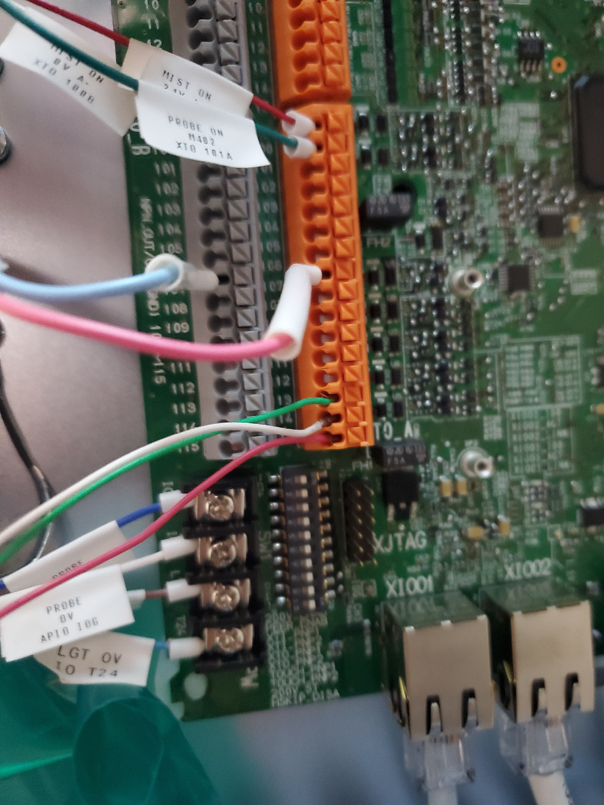
I finally got my light tower wired up. I think I decoded the terminals for the external I/O. The manual is really confusing

***Edit: I was wrong. Further into the manual (Install page 5-27...) it gives better detail. These terminals are configurable to be either PNP or NPN. The dip switches 3-6 tell the machine which way. Mine are all the the right, so everything is PNP, but if the printing on the circuit board is correct, the bottom set (outputs) may be NPN as the default.

Upper level of terminals: Inputs.
Set to be NPN: gray is COM, orange is the input (normally high, pulled low to trigger)
Set to be PNP: gray is input (looking for high signal), orange is 24V

Lower level: Outputs
Set to be NPN: gray is Output, orange is 24V
Set to be PNP: gray is COM, orange is output (goes high when triggered)

The inputs and outputs are supposed to be wired from the orange to the gray for each input or output. In the case of my light tower, there is only one COM wire, and I just connected it to IOG. IOG and the gray terminals (in PNP mode) seem to be one and the same per my DMM continuity check.
***

I setup the data bank page as you described Rick.
So far, my green light is working when a cycle is active.
Nothing on option stop, nothing on door open.
Yellow light comes on with cycle complete.
 
Last edited:
Anyone know where to pick up M3 as an output? Also, anyone know how to input to put the machine in feed hold? I'd like a feed hold button on the back of the machine. It's in a different room, so I don't like going back there when the machine is running but would like to. Thanks. Also, editing my above post to make some corrections.

Edit: found them. SPTURN is available for M3. It doesn't cover tapping though. EXSTOP is the feedhold
 
Last edited:


Back
Top