What's new
What's new

Chatter detection- Creating stability lobe diagrams

ksofiakis

Plastic
Joined
Jan 18, 2016
Hello everyone,
I would like to know how to create stability lobe diagrams. I need to create such diagrams for a project at my university. I can get force-measurements and accelero-measurements by such sensors from dynoware and istruNet. I have read many papers about this procedure but i still don't get it.
I would be glad to any suggestions
 
Is this what you're looking to do? -> http://www.ijirset.com/upload/march/37_Stability Lobe.pdf

If so, good luck. People have been fiddling with this for a very long time and judging by many milling videos posted on you tube, the effort to make milling machines "not" sound like a "nail" machine or "hammer mill" isn't going so well.

Add to that variable geometry cutting tools "appear" to exploit tool instability to increase material removal.

Matt
 
Hello everyone,
I would like to know how to create stability lobe diagrams. I need to create such diagrams for a project at my university. I can get force-measurements and accelero-measurements by such sensors from dynoware and istruNet. I have read many papers about this procedure but i still don't get it.
I would be glad to any suggestions


This seems to be a pretty hot topic at least in academe...

Is this a degree, or masters or Ph.D. level project?

How good is your physics/math/maths.. ?

So typically in a lot of journal articles the content tends to be very compressed, dense and abstract, as there is an assumed body of work and assumed level of understanding.

So picking at random this article http://www.ijme.us/cd_06/PDF/IT 301-050.pdf


"Creating a Stability Lobe Diagram" Jianping Yue Division of Engineering Technologies and Computer Sciences Essex County College Newark, New Jersey

(This person's research was funded by NASA). If you read the conclusion and then skip to the references at the end you will find there is a substantial number of Ph.D Thesis submissions. A lot of the work in this area seems highly theoretical or tries to derive predictive models for chatter. However a Good Ph.D. Thesis should have a very good background section of the subject, before development of "focal theory/actual thesis or hypothesis" and should also contain a lot of experimental detail of how they performed the various experiments and compiled and processed and analyzed their data. In other words "How to do it", and you will probably find the best stuff in the appendices.

I'm not sure how inter-libray loans are for Ph.D. Theses are from Greece?, but maybe there are some Greek Ph.D theses or current Ph.D. students/candidates (other than yourself) that are also trying to get a handle on the subject too... Maybe you can get some help from them too (meet face to face and get some help/supervision?).

As a final tip it's worth identifying exactly what pieces and fragments you don't understand, isolate those elements and then build a learning path to master that element, and then put the pieces back together one by one until you have a coherent understanding of the "Whole". Basically approach it like reverse engineering. Depending on how good your applied math or physics is it can take you from days to weeks to even months to get a real handle on such a subject. It is also possible you can carry out the experimental work in a more practical and intuitive way so you don't necessarily have to go super deep into the math, but it certainly helps to get a better feel for what's going on.

Good Luck, sounds like a very worthwhile project.
 
Thanks for replying all,
this project is between me, a friend of mine and a professor at my university. The seriousness and the level of our job depend from the potential (lab,machine, other professors) and the help that we will get. Yes, you are right chatter and stability of such systems are very big issues that require a lot of knowledge.

The main things that i have in my mind are at first creating a stability lobe diagram experimentally and then analytically or semi-analytically (also with experiments).

My specific questions for now are:
-experimentally: as i have understanded the procedure is creating point by point the SLD by picking detections of cases (stable or unstable) at different spindle speeds and axial depths or radial depths. Is that right? How do I know that this cut is stable or unstable? If doesn;y follows the frequency of the tooth (after the FFT of the acceleromeasurement)?

-semi-analytically or experimentally (don't know yet): is there any possibility of calculating the real part of th transfer function by the measurementw of cuts. We don't have hammer for applying modal analysis.

These are my main issues for now. I will need for sure help in a later stage. I have also in my mind searching for help in other universities and we have reached one professor but he has really a lot of work in this stage of time.
Thanks again for the replying and just to know I have already read the papers (very good work with great bibliography) that you sent me but i really need something more specific.
Thanks again and I'm really glad to be part for such community.

Sincerely Kostas
 
Hello everyone,
I would like to know how to create stability lobe diagrams. I need to create such diagrams for a project at my university. I can get force-measurements and accelero-measurements by such sensors from dynoware and istruNet. I have read many papers about this procedure but i still don't get it.
I would be glad to any suggestions
.
it has been my experience their is tool vibration then their is part vibration. i often see part vibration at a particular spot or corner of a large part. depends very much on part shape and how supported.
.
for finish cuts and even semi finish cuts i often have to slow feeds and speeds cause the part is vibrating too much.
.
quite normal for a face mill to be able to feed at 48 inch per minute on one part but need to be below 25 inch per minute on a different part or even same part but at particular spots. i get this all the time increasing feeds and speeds and seeing problems start to appear then i have to back off a little for tool and finish and dimension reliability
 
I would contact a tooling manufacturer that produces actively damped tools, if I was looking to get the "semi-analytically" side of it addressed.

I have no idea if they would be responsive, or interested in working with you, but as Matt said above, this is a hot topic in the upper echelons of machine tool technology; but a MFR might be interested in providing samples/machine time etc, in exchange for your data.

That's a lot of math you are looking to tackle. yay :)
 
Thanks for replying all,
this project is between me, a friend of mine and a professor at my university. The seriousness and the level of our job depend from the potential (lab,machine, other professors) and the help that we will get. Yes, you are right chatter and stability of such systems are very big issues that require a lot of knowledge.

The main things that i have in my mind are at first creating a stability lobe diagram experimentally and then analytically or semi-analytically (also with experiments).

My specific questions for now are:
-experimentally: as i have understanded the procedure is creating point by point the SLD by picking detections of cases (stable or unstable) at different spindle speeds and axial depths or radial depths. Is that right? How do I know that this cut is stable or unstable? If doesn;y follows the frequency of the tooth (after the FFT of the acceleromeasurement)?

-semi-analytically or experimentally (don't know yet): is there any possibility of calculating the real part of th transfer function by the measurementw of cuts. We don't have hammer for applying modal analysis.

These are my main issues for now. I will need for sure help in a later stage. I have also in my mind searching for help in other universities and we have reached one professor but he has really a lot of work in this stage of time.
Thanks again for the replying and just to know I have already read the papers (very good work with great bibliography) that you sent me but i really need something more specific.
Thanks again and I'm really glad to be part for such community.

Sincerely Kostas


So what you are saying is that chatter does not occur at the fundamental (excitation) frequency of the cutter/tooth frequency? So chatter presents itself as squeely noises that are presumably high pitch harmonics or partials of the fundamental frequency... And you are hoping to find a pre-tweeked "blinged out" math engine that can do inverse Fast Fourier Tansforms specifically for what you are doing? :-) That's not so far fetched... There are probably a few out there but will they give it to you :-)

Just as an side I play the tenor saxophone and know how to create squeely noises deliberately in-tune/deliberate harmonics/partials that are WAY above the fundamental mode of vibration (other musicians know how to do the same on their respective wind or brass instruments). And conversely to counteract squeely noises you use 'Vibrato", a gentle low frequency amplitude modulation. So related to that a tech told me that on the OKUMA M560v they have what he said was a microphone that picks up squeely noises, and then has the capability to induce this slow sinusoidal modulation to smooth out the chatter. If you are stuck for FFT math engine the university of Cardiff had a really excellent combined physics and music department where they did a ton of analytics... They might have a math engine that can characterize these partials and harmonics for you, and as others have been saying it will be really interesting to see how you isolate the various contributing factors, such as size, dimension and rigidity/youngs modulus of the work piece... and as MrBronze was also saying contact the dampened tools manufacturers. I have always found commercial industry to be very helpful for new research, in terms of free materials and advice.


I have been on a number of research fellowships and its going to take you time to pull all the pieces together but I have no doubt you will and become an expert on that, but I'm not sure that you will find an instant "Kit" for that, but maybe its out there somewhere. Just takes time to assemble all the fragments and let them stew for a bit and play with all this.
 
One thing I think needs to be studied a little is Chaos Theory. Don't laugh and I don't mean to be flippant. It is real and plays an effective part in the trials we go through as machinists. Some things can never be fully predicted.

Paul
 
The folks at mfg-labs.com and blueswarf.com have done a pretty slick job of analyzing tool assembly/spindle harmonics. They output a stability graph. I've used their products a few years ago for establishing best speeds for tooling a machine with a 32k spindle. The stability graph was usable, but the best tool was the "dashboard" that did the analysis of the stability graph and the proposed cutting conditions to predict stable or unstable cutting.
 
The main problem with me is that I'm young and unpatient. :( I will learn.

As for my questions, I speak generally. I have some testing measurements, not final. Imagine that we don't know the cutting parameters of the experiments, nor workpiece, nor tool, anything. I m talking about what to expect to see.
-Experimentally: Let's think of having a measurement of Spindle speed x, axial depth y with constant feed per tooth z. We extract the measurements from dyno-sensor (force) and accelero-sensor (acceleration, not sound or microphone). How to decide if this cut was stable or unstable?

My next question is about (as far i learned from the former research (papers)) the calculation of the transfer function (i suppose for the analytical method or not?) and its real part which is used for the calculation of the critical axial depth. Is the calculation of the transfer function and its real part compulsory for the creation of SLD? Next: is this possible to calculate the real part of the Transfer function without modal analysis and hammer test (through the measurements maybe?)? (i suppose because all these (forces, accelerations) are connected.)

As you now maybe understand, I 'm completely lost. Any ideas or suggestions are welcomed. Thank you all again.
 
The main problem with me is that I'm young and unpatient.:( I will learn.

I guess you're about to! If you learn nothing else from this it will be,
(1) Experience with a machine tool and neat lab tools! That's COOL!
(2) Real world asymetry with machine tools (no two are exactly the same no matter what the maker says), and with materials (two pieces from the same barstock – hardness test the same – same published value for “Cutting stiffness per unit width of cut” - give different measurements on the same machine tool with same tools & settings… BUMMER)...
(3) Ending up knowing you can't define all the variables (BIG TIME), but you can be pretty handy & useful anyway.

The main things that i have in my mind are at first creating a stability lobe diagram experimentally and then analytically or semi-analytically (also with experiments).

Good idea – By the time you do the baseline and collect the data with the experimental part you'll visualize things, it makes a difference being there. If you have a spectrum analyzer or a scope with an FFT function, you pretty much see it.

My specific questions for now are:
-experimentally: as i have understanded the procedure is creating point by point the SLD by picking detections of cases (stable or unstable) at different spindle speeds and axial depths or radial depths. Is that right? How do I know that this cut is stable or unstable? If doesn't follows the frequency of the tooth (after the FFT of the acceleromeasurement)?

Trust me, you'll know – it's similar to adding water to acid, quick, violent & scary. For milling, tooth engagement or exit is the dominant and 2nd order frequency (depending on cutting conditions defined by up or down milling). I'd prolly be tracking displacement first, not acceleration or velocity for this. You will find this frequency signature anywhere you place a seismic transducer or piezo accelerometer on the machine tool (closer to spindle or part fixture is better, but not a deal killer).

With one testing system a tuner can be used to filter to that frequency while second broad spectrum system will show any induced excitation making the machine tool structure to “go nuts”. Any notion that the tool and spindle can be isolated without regard to the whole machine tool ecosystem is silly.

-semi-analytically or experimentally (don't know yet): is there any possibility of calculating the real part of th transfer function by the measurementw of cuts. We don't have hammer for applying modal analysis.

That's a problem, without a hammer test you don't have a static modal analysis which is crucial to baseline the machine tool.

Good luck,
Matt
 
Hello again.
Thanks for replying Matt. You are awesome.

After the measurements I do use Matlab code for the FFT because we don't have the ability for instant Fourier measurement. This possibility is only available with the force measurements (Dynoware software). But as I read the detection is possible only with the FFT of the acceleration or dispacement, velocity, isn't it? The sensor of acceleration is applied on the fixture with wax. We do't have any other sensor for displacement or velocity detection.

At this point I want also ask: does the chatter be detected only if the tooth frequency is different from the real one? For example if I use 7500 rpm two fluted tool then the tooth frequency is : f=S*n/60=250 Hz and its multiples. So in this example if I detect a peak at 350 Hz, would it be because of chatter? That's the only way of detection that I know.

Moreover for the analytical way, I approached a professor (to tell the truth,,, the communication was a bit difficult,,, he did't speak English frequently). He told me about the calculation of the minimum of the real part of transfer function G. The method he mentioned is:
a: acceleration
x: displacemet
F: force
f: frequency
t: time
G: transfer function

1. Measurements of F(t) και a(t) in directions x,y,z from Dynoware (force software) and InstruNet (acceleration software)

2. Fourier transform of force and accleration to complex form
a(t)=a_real(f) + a_img(f)
F(t)=F_real(f) + F_img(f)

3. Calculation of displacement using acceleration
x(f)= a(f) / f^2 ----> x_real(f) + x_img(f) = [a_real(f) + a_img(f)] / f^2

4. Calculation of transfer function:
G(f) = x(f) / F(f) ----> G_real(f) + G_img(f) = [x_real(f) + x_img(f)] / [F_real(f) + F_img(f)]

at the end using maths the final type for the calculation of the real part is:
G_real(f) = [x_real(f) * F_real(f) + x_img(f) * F_img(f)] / [F_real(f)^2 + F_img(f)^2]
Then we calculate the minimum from this part, which we use for the calculation of the critical axial depth: b=-1/(2*Kc*min_G_real

Two questions: 1. Is this method right (as i said we had communication problem) because I coded this at Matlab but the result of the min_G_real was way too high. Or should I correct my code (ckecking it)?

2. After the calculation of the bcritical at a certain measurement what's the next step? What exactly did I find? Is this just a point of the SLD? How do I calculate a lobe through this method? Is this method usable for stable or unstable situations or both of them?

Ohhhh... My head...

Thanks a lot Matt and all of you...

When you said "The result of the min_G_real was way too high..." What was it, and what do you intuitively feel it should be?

Honestly this is going to take you a couple of weeks to get convincing models or simulations that actually hang together (that are even vaguely predictive)if then. If you are able to accomplish that in less than a couple of days I'm sure you would have many hundreds of job offers from all over the world :-).

Let me get this right, You are Greek but English speaking with a French professor in Greece communicating in English ? I have to admit I find this subject area very intriguing and might delve deeper.

On a related tangent, I think the thing that kinda frustrates me about the machine tool industry on the marketing side of such things is the term "rigidity"... I wish there was a MTF type/ 3d plot/frequency response curves that answer more directly in blunt terms (without various resonances) how "RIGID" a machine really claims to be, coupled with surface finish. I wish there was a simple "Metric" or series of 3d plots to better express the notion of "Rigidity"..?
 
I'm going to chime in with my non-college educated understanding, which is very little... But, I have a serious question about the goal of all of this... What is the goal anyway? Is it to be able to predict the optimum speed for a tool, based on it's gage-length? (Total length of tool, as measured from the tool-tip to the "gage-line" of the spindle.) And I assume we're sticking to milling tools, correct? "Chatter" occurs/behaves/reacts totally different when we're talking about turning/lathe operations.

But anyway, one thing that I would keep in mind, is that no two machines will act the same. When you're milling/cutting, there's a total force-loop that must be taken into account. Which means, from the cutter-to-part contact, and then all the way back through the machine tool. Meaning, from the part, to the table, to the guide-ways, to the bed-casting, to the column, to the headstock casting, to the spindle housing, through the spindle bearings, through the spindle-taper, to the tool-holder, down through the cutting tool, and finally back into the cutter-to-tool contact.

There are so many variables that need to be defined to make a "predictive" model of optimum spindle-speed relative to gage-length, that coming up with a "universal" model is just futile. However, a "working" model, where initial testing must be carried out, in order to try and establish values for some of those variables for an individual machine, cutting a certain material, and so on, could ultimately be helpful.

That is a lot of work however, just in defining all of the variables. Let alone, working out how they all influence each other within the equation...

-------------------------------------------

When ksofiakis asked about how to define "chatter" earlier, let me give you a hint... Don't worry so much about all the physics behind what "it" is, but rather, look instead to see what's going on at the part/cutter. When you "hear" chatter occur, the surface finish goes to crap. You go from a normal, predictable surface finish, to a totally random and unpredictable finish - both visually, and physically - despite "hearing" what seems like a normal, steady harmonic frequency. (albeit, "unpleasant" to the ears it may be...)

And, the worse/more irregular the chatter sounds, usually the more irregular the surface finish will be. It's been my experience in machining that this "god-awful" irregular chatter is an indication of improper cutting parameters - namely depth/width of cut... No amount of tuning of the spindle speed & chip-load will "tune-out" this type of chatter, unless you fix the cutting parameters first.

Chatter that sounds more "regular" will be easier to tune-out with simple adjustments to spindle speed & chip-load.

So maybe that's one way to help analyze your findings...? The more "sinusoidal*" the chatter is, the closer you are in terms of depth/width of cut to "stability"? The more "tangential" or "irregular" the chatter is, the more emphasis must be placed on depth/width of cut, instead of simply spindle speed?

------------------------------------------

I use the terms sinusoidal & tangential, maybe incorrectly, but here's my line of thinking anyway... If you look at the way a loud-speaker responds to sine-waves, the speaker's travel/displacement output should be a dead-match to the phase of the sine-wave input. OK, one can expect the output to be slightly out-of-phase with the input because of the speaker's physical inertia, but it should be a slight, constant, regular phase error. When the speaker's output starts deviating from the input, you get distortion, and terrible sound quality. (I guess the correct terms for this would be 2nd-order, then 3rd-order etc. vibrations?) If the distortion gets bad enough, it starts approaching white-noise levels of sound quality until there's a mechanical failure of the speaker...

-----------------------------------------

It would be interesting to see if the frequencies measured nearest the part/cutter were actually sinusoidal under optimum conditions...

Or would perfect sinusoidal frequencies send the tools/part/machine into mechanical/harmonic resonance and actually cause chatter?

As food for thought - differential-pitch cutters (un-equal flute spacing tools) were developed with the idea that they would help prevent harmonics - and from real-life use, they work...

---------------------------------------

Anyway, like I said, that's my un-college educated 2-thou...
 
So related to that a tech told me that on the OKUMA M560v they have what he said was a microphone that picks up squeely noises, and then has the capability to induce this slow sinusoidal modulation to smooth out the chatter.

Chatter produced by milling vs. turning respond differently. Milling chatter must first be addressed through part/setup rigidity, then through depth/width of cut, and then by spindle-speed & chip-load. But anyway, If you're lucky enough to be at the spindle-speed & chip-load level, then chatter is suppressed by making a single change to a new spindle-speed and/or chip-load. No oscillations when suppressing milling chatter... Ypu need a constant change.

With turning, the first level is still part/setup rigidity, then less importance on depth of cut & feed, and finally, very little difference with regards to spindle/cutting speed. The difference is, that chatter when turning is much more finicky, and you do suppress it through oscillating the spindle speed. A constant change just means changing the frequency of the chatter - it's only suppressed/broken-up through oscillating the
spindle speed. On older, low-tech lathes, that means jogging the spindle-speeds up and down manually via the overrides - which generally means 10% increments, typically 2-3 times a second, because that's the increments of the overrides, and the speed of your hands... :) Where the modern machines make better use of this oscillating speed principle, is that you can alter the parameters of the oscillations - meaning you can define the frequency & amplitude of the oscillations, which probably means better response from the cut, and better luck in actually suppressing the chatter than what was previously possible using your two hands and the overrides...

---------------------------------------------

Regarding an objective measure to rigidity...

In terms of chatter, it gets messy. In some applications - particularly boring on a lathe - you can actually be too rigid... Case in point - We have a new Mazak lathe, and I was having trouble with chatter in a boring operation, despite the machine being new & tight, with it's pre-loaded linear-roller guides. Having a rigid tool, in a decent holder & pinch-sleeve, and good workholding/part-rigidity, I was still fighting chatter... The answer? Electrical tape. No, seriously.... I pulled the tool-holder off, put a layer of electrical tape between the mounting surfaces, and tried again. Viola! Silence...

Weather it was the actual harmonic-dampening effects, or the slight deflection of the tool under load at work, I'm not sure, but it worked. I wonder to myself, if this machine was a box-way machine with turcite on the sliding elements, if this chatter would have never been an issue. So, at some level, a little dampening/deflection makes a difference...

------------------------------------------

From another perspective though, one could quite easily & objectively measure the effective "rigidity" of a machine using an indicator, and "forcing" the machine's axes into a solid object. Simply find out how much thrust each axis has under 100% load. Bolt a solid object to the table/chuck, and force each axis *gently* into the object. Use a test-indicator to measure the deflection...

Here's a cool video of the Binns "Super-Lathe" that talks a little bit about rigidity... Even if it doesn't help address your concerns of objective rigidity, it's a cool video nonetheless... 23 minutes long, but definitely worth it...
:popcorn:
https://youtu.be/j87WW-jGmrU
 
Hi again to all and thanks for applying,

As for "cameraman", I made the cutting tests with an end mill of 2mm diameter (I know that is a very small diameter and it's better to operate with bigger tools in order to detect chatter) and expecting a minimum real part of the transfer function of about 10^(-2) mm/N and the programm's result was 10^8 mm/N (what a difference!!!).

As for "Jashley73" really good advice. I appreciate you sharing your experience. Yes, the operation is obviously milling. The goal of all this, is the creating of Stability Lobe Diagrams of our milling machine of different tools. I have no idea as I said how to produce them. My question is if is there anyone to tell me the procedure (the steps to follow) after the measurements (experimental and analytical way). How do I create a lobe for example of the SLD? Moreover all papers (research) are using the transfer function of the system in order to obtain such an analysis. Could I calculate the transfer function without modal analysis (maybe the way the professor told me - my previous reply?)? And if so, I calculate the critical axial depth. What is this exactly? Is this a point of the SLD of an analytical way?

Sincerely Kostas
 
@ Jashley, on your first post – I think he is trying to learn & the ultimate goad is to get predictive. The first part will happen, and even if the ultimate goad is not fully achieved as imagined some of the predictive thing will happen. For the moment ksofaikis has to sort out the kit and data collection while, (I guess) getting wise with a machine tool...

I like your boring bar example, & with live spindles I will use a bar too weak to transmit the instability into the part or the machine tool using HSS at or near an effective neutral rake. The bar hums but you can still get the surface finish when it's right. And yes! Your reasoning about the turcite being a game changer is spot on.

@ ksofaikis, I can't comment on your model but IIRC - it looks similar to the 2D model that the GE Carboloy guys were fiddling with for orthogonal cutting (been a long time back). You have to get your test kit sorted out first & use it a bit to decide the data collection part long before you start to actually build a model.

The chatter you're chasing for lack of a better term is “chaos”, and the worst results from “self excitation”. Everyone I knew using vibration sensing did so to remove “forced vibration” as it was easy to pin down if it existed, or to simply track machine tool condition. I know the GE guys were never happy with their own “futuremill” milling solution of using variable space tooth cutting as it required an early change of inserts compared to a solution where each equally spaced insert would be used up before changing tools. They never got there that I know of.

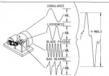
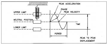
On the testing of vibration, I'll attach some stuff. Displacement, velocity and acceleration are all connected (the sine wave thing). Which to use & where is the key. Normally displacement is used at 600CPM and below for conditions of dynamic stress – Velocity is related to vibration severity and used from 600 to 60,000CPM – Acceleration is related to force and normally used from 6000 to 600,000CPM. Your accelerometer is going to see everything and you have to sort (filter) to what you are interested in because things add and subtract inside the total amplitude of the signal… Bummer… “That's USUALLY” - often for a machine tool I'd try to use displacement (which is good to 60,000CPM or so with a seismic transducer) and use ISO vibration charts to see if I needed to consider velocity or force and then go to an accelerometer for input.

I'll also attach how (old timey) mill chatter was (attempted to be) sorted out for forced vibration. CAUTION to machinists – It'll make your eyes hurt looking at the picture, but you've all BTDT...

Good luck
Matt
 

Attachments

  • ComplexVibration.jpg
    ComplexVibration.jpg
    65.7 KB · Views: 1,385
  • Vibration1a.jpg
    Vibration1a.jpg
    39.7 KB · Views: 1,064
  • MillChattera.jpg
    MillChattera.jpg
    91.7 KB · Views: 2,118
  • MillChatterb.jpg
    MillChatterb.jpg
    88.3 KB · Views: 518
  • MillChatterc.jpg
    MillChatterc.jpg
    60.4 KB · Views: 790
If you were really interested in developing stability lobes, real world techniques, are tied into academia, I'd get in touch with Dr Tony Schmitz at UNCC. I took a grad class with him and started my masters in his Machine Tool Research Center at UF. He's a great guy, real smart dude, and loves machine tool research, especially structural dynamics.
One of his students was trying to set up a website where you could log on and input your tool data, and get stability lobe data. This was back in 2003-4, so I'm not sure where it went, if at all.
 
Ohhhh... My head...
......

It only gets worse the deeper you dive down the rabbit hole.
Let us know how and where this goes for you.....Too many just plain give up or the end results are so confusing that no normal human can use any of it.
Now we have phones that can log such info off a spindle/cut. Hmmm.
Who will make the software to do the number crunching needed and drop out the nice feed/speeds?
Think big market hole here enabled by current low cost tech if you dive in deep enough to make it simple for everyone else.

It works great, it is just crazy messy at the moment and not easy to use or understand.
If you go down this path think continuously "easy to use app". How do I make this simple.

Really, what the heck is a FFT or DFT? Real, imaginary, transfer functions, sampling speeds, z-domains......my eyes are glassing over.

KISS if you want to make you work usable or profitable. Never loose sight of that.
Otherwise all your excellent work will just be a footnote in a textbook or some tech papers.
Bob


Back
Top