What's new
What's new

Clamping ideas for long parts possibly hydraulic

imachine909

Cast Iron
Joined
May 17, 2010
Location
South East
Looking for some ideas how to clamps some parts quickly. Currently use lots of vises. Parts range in length from 2 feet to 12 feet long. Below is a picture of the side view of the part and sizes and another of the part in the current vise jaws we use. Thinking maybe some hydraulic vises or cylinders with some jaws on them. Any suggestions?
 
There are lots of configurations of hydraulic actuators and clamps, so I'm sure something can be found to work for you.

A couple thoughts - the way you show the part being clamped may have a risk of upward bowing of the horizontal section, is that a concern? And if you use hydraulic clamping, consider worker safety during loading. One way is to have two or three manual clamp stations to locate and hold the part along the length, then (when the worker is clear) actuate the remaining hydro clamps.
 

I don't know if this is of any help, but thought it interesting for larger / longer aerospace parts like wing ribs etc.

They are using the Schunk Vero -S work holding solution …

Haven't watched the video all the way through but seems they have devised a method where the zero point systems partially unclamps to relieve stresses and locked in part distortions and then I guess permits lateral shifts and then re-clamps for a spring pass ?

Not 100% sure how it really works ?

Wondering where and how they grab their reference points after 'Stress relief" / probing "tactics" ?
 
I don't believe we have enough surface area for a vacuum fixture on this part.

I think what pcasanova might have meant (also) perhaps are various gripping systems that are operated via a vacuum port. (a bit like Schunk systems). Not sure how vacuum systems are implemented / vacuum line in a shop.


I.e. the grippers or zero point clamping systems are operated via a diaphragm so when the valve is opened to "suck" / vacuum then the diaphragm / plunger pulls down against pre loaded springs to release the part or fixture etc.

[I'm no expert on this.] I think what Milland was / is saying is valid compared to hydraulics being able to exert massive pressures and crush people's digits. Although the vacuum zero point systems from Schunk have forces of the order of 40,000 N (Newtons) each (2000 -ish lbs ).

I think with the vacuum based grippers and clamping systems that you may be able to set the clamping spring pressure. .. So the vacuum is only used to "Open" release the part / fixture against the fore of the springs which grip the part or fixture.

________________________________________________________________

@jowens sorry for being dumb here, is that an extrusion ? OR are you first removing a lot of stock ? Are there tolerances that matter with this ?
 
no vacuum block is what I meant. I thinking of a block 2'x3-4wide and about 1.5-2 thick, chamfer the front edge to miss that rad. mill a pocket 1.25 x 22 back enought to miss the hole feature or slot not enough drawing info
1.25x22x14= about 385lbs of force. but not sure if any features would be in the pocket area, if so scrap the idea.
 
@pcasanova the reason I was leaning towards some sort of moveable jaw was due to having 3 different operations along with 72 different parts numbers. The jaws we use now run all 3 ops that's the reason for the other set that the part isn't sitting on in the picture. How aggressive you think I could machine using a vacuum? Would it be near the same as having part in vises?

I understand all the safety issues and concerns.

Basically the vises work fine just takes a lot of time to clamp each part. looking to improve the part load time.

@cameraman this is extrusion roughly 1/4 on all faces before machining starts.
 
We'd need to know what specific operations are performed before a useful recommendation on fixturing could be done. Is the entire surface machined, or just sections drilled or pocketed? What sort of final tolerances are needed?
 
My question is, what kind of vises are you using? 6 inch kurt or similar? How far apart are they spaced. What are you doing with the part?

For less clamping time and depending on what you are doing, If you currently are using 6 inch vises with an inch between them, I would skip that and make some long jaws (10", 12", maybe even bigger) for each vise and space them further apart. Then you would simply have fewer vises to clamp, while still fully supporting the part.
 
I have used Destaco clamps for years for fixturing various things with good luck

If the parts have the same dimensions other than length it is pretty easy to develop a fixture that holds all of them and use the clamps to hold down and or against a stop.

Sure hydraulics and pneumatics are good, but unless doing many thousands probably over pricey
 
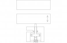
if not that route you can go something like this

clamp.jpg

I'm thinking something like this is what camerman was thinking, but instead of vacuum on one side of the piston, air on the
other side to overcome the spring pressure. so you would need pressure to release and the safety would be there if you did loose air
your part would stay. and the valve would have to have a relief exhaust (mac has a big selection)to let the air off the piston.
 
Basically the vises work fine just takes a lot of time to clamp each part. looking to improve the part load time.

How much time is spent loosening/clamping vs. cleaning chips in preparation for the next loading? Fixture design should take chip management into account. Hydraulic and pneumatic fixturing introduce plumbing lines that can catch a lot of chips.

Also, is it more about the time spent tightening vises, or the physical exertion? I have my guys use electric impacts whenever possible. 5 seconds spent spinning an impact is a lot easier than 5 seconds spent torquing a handle. Most of the time, the impacts are faster anyway, but the point is that you benefit even without the time savings.
 
Dumb questions really... To 'peeps" that know etc.


1. For long precision work pieces like OP's inquiry (work pieces as long as 12 feet) is there a specific order that the clamps should be clamped in ? Like ~ from the middle outwards alternately till you reach both ends ? [Middle, left, right, outer left, outer right, far left , far right (kind of thing) ?].

There is no 2.

____________________________________________________________________________________________


Some idea of cutting conditions / tools used and pattern of "stock removal" would give a vague sense of cutting forces involved hence possibilities for more automated fixturing ? A vague idea on tolerances would be very handy too (like what Milland was pointing to too), as it's not always the case a high precision machinist vice is needed ?


It used to be with standard "Machine elements" /catalogues you have those manually operated hold down clamps and their pneumatically driven cousins used on custom in situ machined fixture plates.
 
if not that route you can go something like this

View attachment 262018

I'm thinking something like this is what camerman was thinking, but instead of vacuum on one side of the piston, air on the
other side to overcome the spring pressure. so you would need pressure to release and the safety would be there if you did loose air
your part would stay. and the valve would have to have a relief exhaust (mac has a big selection)to let the air off the piston.

Very nice.

I was puzzling why some of these high end designs use vacuum over positive pressure..? The only thing I could guess at is that with a vacuum system that theoretically the counter pressure on a diaphragm is always* going to be 1 ATM (Atmosphere pressure) MAX. Shop air being what it is (or can be) and how it may or may not be regulated I wonder if the folks at Schunk and other figured that Vacuum is likely to be more consistent and not jam their mechanisms as much as would be the case with a positive pressure system that could have much more variance in positive pressure ? (maybe ?)

_______________________________________________________________________________________


* Do they have to calibrate for altitude ?
 
My question is, what kind of vises are you using? 6 inch kurt or similar? How far apart are they spaced. What are you doing with the part?

For less clamping time and depending on what you are doing, If you currently are using 6 inch vises with an inch between them, I would skip that and make some long jaws (10", 12", maybe even bigger) for each vise and space them further apart. Then you would simply have fewer vises to clamp, while still fully supporting the part.


Currently use 11 6 inch kurt vises. Long jaws with on .100 gap between each jaw.
 
I have used Destaco clamps for years for fixturing various things with good luck

If the parts have the same dimensions other than length it is pretty easy to develop a fixture that holds all of them and use the clamps to hold down and or against a stop.

Sure hydraulics and pneumatics are good, but unless doing many thousands probably over pricey

Which destaco clamps are you saying to use for this type of job?


Back
Top