What's new
What's new

Cutting Sheet Metal Cone on Haas Lathe

racer8432955

Plastic
Joined
Feb 10, 2020
Location
Kenosha, WI USA
Hello All.
My first post here seeking help as I am a true amateur, just been reading and lurking around for about the last 1/2 year. I'm not a machinist, but a product development guy that for the last 20+ years has been involved in anything and everything working for small companies can dream up. Part way thru last year my company decided to take on metal spinning under our suite of services (sheet metal fab).
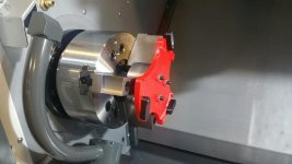
Steel tools are made on our Haas ST20Y (by me). The spinnings (generally .050" thk 1100-0 series aluminum sheet) are done on an Italian made spinning specific machine. While this is a niche market, there is nothing to unique so far in what I have described. However, the manner in which we are cutting secondary features into parts is. We are attempting to cut them on our ST20Y, which I have had some success so far, as opposed to a 5 axis laser as most spinners use. Parts are fixtured in 3d printed holders mounted to a steel arbor, which is clamped in the 3 jaw chuck.
My goals are to reduce the burr, or minimize deburring after the cut. Speed: what I have pictured is cutting about an 8" dia, my best cuts so far have taken about 2.5 minutes total cycle time (single pass cut). This is not too bad in relationship to our costs, but of course we would like to do better. Tolerances; don't fall out of you chair machinists but commonly we will be given +/- .030".
My best cuts so far were using a 3mm / 4 Flute uncoated china/ebay hss end mill. Machine is limited to 4000 rpm. SFM= 123 ft/min & Cutting Feedrate= 20.6 in/min.
So... my question is, does anyone have a good / better / perfect baseline on where to start with cutters, feeds & speeds, and technique for accomplishing this??
Thanks!

fixture-1.jpg
pre-cut1.jpg
cut1.jpg
cut2.jpg
 

Attachments

  • fixture-1.jpg
    fixture-1.jpg
    94.7 KB · Views: 207
First, don't use the endmill to cut the end off the part, use a parting tool to cut almost to length before you even begin profiling.

Then you don't have to use a tiny endmill, you can use something large for cutting that profile, like 3/8" uncoated carbide (not familiar with 1100 series Aluminum, so maybe uncoated HSS is still a better option)

Finally, deburr in the machine, assuming a slightly broken edge is acceptable. Use a brush in a live tool holder, offset it from your finish pass by the radius off the brush, offset in Z to get your deburring.
 
Yes. And the tiny endmill gripped way out in the ER collet seems none too rigid. Gotta be a better way to part that off.

Really like the 3D printed holder, though.
 
First, don't use the endmill to cut the end off the part, use a parting tool to cut almost to length before you even begin profiling.

Then you don't have to use a tiny endmill, you can use something large for cutting that profile, like 3/8" uncoated carbide (not familiar with 1100 series Aluminum, so maybe uncoated HSS is still a better option)

Finally, deburr in the machine, assuming a slightly broken edge is acceptable. Use a brush in a live tool holder, offset it from your finish pass by the radius off the brush, offset in Z to get your deburring.

Thanks for your input. I would like to try this, but am very limited with tools. No cut-off tools, one radial live tool. Multiple tool changes per part would kill the cycle time.
 
Yes. And the tiny endmill gripped way out in the ER collet seems none too rigid. Gotta be a better way to part that off.

Really like the 3D printed holder, though.

I've questioned this from the beginning, but being a newbie to this I am not aware of all the tools available. Is there a cut-off tool that allows you to make a cut as I have shown below?
The 3d printer comes in handy for the light duty tooling we often need, form tools etc.

fusion-path-side.jpg
 
I'm not CNC conversant, but why do you need the ER collet extension at all? Or the tiny end-mill. Couldn't you make the same tapered cut with a 1/2" endmill choked-up directly in your live tool holder?
 
I'm not CNC conversant, but why do you need the ER collet extension at all? Or the tiny end-mill. Couldn't you make the same tapered cut with a 1/2" endmill choked-up directly in your live tool holder?

I tried this with a 3/16 EM, had quite a large burr not matter what i did? So, I thought I would try small dia cutters. Still trying to find my baseline / best place to start.
The other issue that led me to a collet extension was colliding with the part. The base of live tool is 94mm sq. Add in the height and placement of the coolant nozzle and clearance will be an issue with anything much more than a cylinder. All of our parts will be cones and curved shapes of various sizes.
 
1100 aluminum, even if cold-worked, is gummy. I believe burrs will be unavoidable. They can be minimized by using the sharpest tools you can get and keeping things cool and lubricated by flooding with coolant.
 
Thanks for your input. I would like to try this, but am very limited with tools. No cut-off tools, one radial live tool. Multiple tool changes per part would kill the cycle time.

You're taking 2.5" minutes to make a 45 second cut. Unless Haas lathes are even worse than I've heard.

If you take the advice given, you save a minute to a minute and a half, even after adding tool changes.

You're feeding .001"/Tooth on that tiny endmill (20.6IPM/4000RPM/4T = .00128" feed per tooth) If you step up to a 3/8" (or larger), you can quadruple that easily, and honestly, with tweaking, probably increase it up to tenfold...

Cutoff the part, maybe 1/8" or less past the longest point of your finished part, that'll take 7 seconds...

Then cut your finish profile with a stiffer endmill (less deflection = less burrs)... If you feed this at 4x your current feedrate, your cycle time is now 1/4" of your original, so you're at 37.5 seconds + the 5 (being generous) seconds it takes to do the initial cutoff. Add another pass with a brush in a live tool holder, as I suggested, and run it at 10X your original feedrate, taking 1/10th of the time of your original cycle, adds another 15 seconds to the part, plus maybe 2 to 3 seconds for the tool change (no idea how fast a Haas can do that, but 2-3 seconds is slow)...

So now you went from 150 seconds (2.5 mins as you stated) + hand deburring to roughly 60 seconds, a 60% cycle time decrease, with no hand working after.


You may be limited with tools now, but you've gotta have some leeway to experiment, or you wouldn't be asking here. If one $75 tool holder and one $20 insert can cut your cycle time by 60%, they have to have a pretty quick ROI, no?
 
Also, if you have to run the ER collet extensions, at least step up to a 3/4" or 1" shank ER16 extension, for greater rigidity.
 
Couldn’t you just 3D print a cone that is tilted at a angle so you could just part it off on your cutoff line. That would knock it down to how fast you can swap parts.
 
I feel like a decently built mdf sled/jig and a vertical bandsaw would be far more appropriate to take a flat cut off the end of a spun cone. I don't spin parts or run a cnc lathe for a living, so feel free to bash my idea here...but this seems like it is a very simple process being over thought.

Obviously parts with multiple cutouts and more detail would be a different story.
 
While a larger endmill is indeed stiffer, the Al part is the limiting factor, not the cutter - only so much "energy" you can put into it before you deflect the sheetmetal edges. Yes, a cone is an inherently stiff geometry, but not at that cut diameter to wall thickness ratio (and soft/gummy base material).

I like the idea of printing an angular fixture so one could cut with a parting tool. It might be better to set up a thin saw on the live toolholder and use that instead, ideally with a good air nozzle or mister to keep the teeth clean.
 
Two things.

1. Probably everything you try is going to suck at some level because the material not supported and it's sheet metal. Personally, I would be looking for wood, 3D print, or maybe molten plastic cast of the ID of that cone and make a "form fit mandrel". I probably won't stop all the vibration but I bet it gets a bunch of it. We have done similar to get a job done.

2. You will probably fight and fight and fight with ANY helical endmill due to the shearing action that pulls up on the part as it cuts, which causes your vibration. We need straight flute endmills around just for crazy stuff like this. A straight will NOT eject chips too well so setup accordingly.

I might reach for a tiny parting tool to get the bulk off, then see what you can do with a straight flute endmill to run the contour. I would take some clearance passes in the new mandrel with a helix endmill to make a channel for chips first.


Back
Top