Hello,
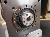
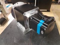
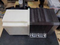
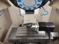
I would like to present the latest addition to my workshop. It’s a 150mm DIY 4th axis (based on a harmonic drive reduction) with an electromagnetic disk brake.
The basis of the project is a 100:1 reduction harmonic drive imported from Japan. For compactness, I went for one of their CSD units (CSD-25-100-2A-GR-SP) which has an overall length of just 17mm and an OD of 85mm. The rated torque for this model is 47Nm at 2000RPM, with a limit of 110Nm for repeated torque.
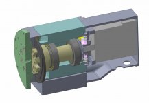
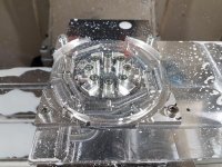
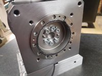
The input of the harmonic drive is driven by a 4.6Nm closed-loop stepper motor (Nema 34). The output side is attached to a 40mm OD shaft supported by a pair of P5 precision tapered roller bearings (32008 XA P5), with the assembly being held inside a 120mm cubed steel housing.
The interesting part of this project is, in my view, the electromagnetic brake. Most of the DIY 4th axis builds I found online that are based on harmonic drives don’t include a brake. This results in some performance issues, as the harmonic drives are noticeably not very torsionally stiff devices. As an example, for drive I chose, a 10Nm torque at the output results in a torsional displacement of 76 arcsec. That’s a linear displacement of 28 microns at a radius of 75mm. This means that we are limited to doing only very light machining or very small parts...
Since I plan to use this 4th axis mostly just for indexing, having a brake mostly solves this problem of stiffness.
The brake is composed of an aluminium disk attached to the main shaft through an axial flexure (I had to go through 2 versions of the flexure until I found the right design). By default, the disk is pressed by a steel plate against a stationary aluminium housing. This plate is preloaded by 8 stacks of belleville (spring) washers held on M5 socket head screws. The spring preload, which sets the braking torque, can be adjusted by tightening or loosening the M5 screws.
Having aluminium as the braking surfaces might seem an odd choice, but this combination of materials actually has a pretty high static coefficient of friction (around 1.0 depending on where you source the data). Since the purpose of this “brake” is to lock the 2 surfaces together and not do any actual breaking (i.e. surfaces sliding together), I don’t anticipate too many problems of wear or galling of the aluminium surfaces. But I might be wrong , and if I am a new disk and housing can be easily made out of different materials.
When it comes to how the brakes are actuated, there are plenty of methods available to choose from (hydraulic, pneumatic, hydraulic over pneumatic, etc.). I went for an electromagnetic actuation as it was quite easy to integrate neatly into the 4th axis and straightforward to connect to the machining centre this will go into.
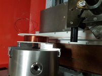
The actuator consists of a 700 turn, 0.65mm enamelled copper wire coil inserted in the front face of the steel bearing block. At rest, the gap between the steel plate that preloads the brake and the steel bearing block is 0.2mm. When the coil is energised with a current of 2.4A, the magnetic forces pull the steel plate away from the aluminium disk, hence releasing the brake. Once the steel plate is stuck to the steel bearing block, the current can be reduced to half (about 1.2A) as to not overheat and burn the coil. In practice, this is achieved by connecting a resistor in series with the coil through a delay relay.
The measured holding torque for the optimal preload was about 90Nm which seems reasonable for a 4th axis of this size that will be used mostly for machining aluminium parts. The measured backlash (which comes from both the hysteresis losses inside the harmonic drive and the discrete steps of the stepper motor) was about 18 arcsec under no load.
I hope this can be of use/inspiration to anyone thinking of building a DIY 4th axis.
I will include a few images of this project next.
Cheers
I would like to present the latest addition to my workshop. It’s a 150mm DIY 4th axis (based on a harmonic drive reduction) with an electromagnetic disk brake.
The basis of the project is a 100:1 reduction harmonic drive imported from Japan. For compactness, I went for one of their CSD units (CSD-25-100-2A-GR-SP) which has an overall length of just 17mm and an OD of 85mm. The rated torque for this model is 47Nm at 2000RPM, with a limit of 110Nm for repeated torque.
The input of the harmonic drive is driven by a 4.6Nm closed-loop stepper motor (Nema 34). The output side is attached to a 40mm OD shaft supported by a pair of P5 precision tapered roller bearings (32008 XA P5), with the assembly being held inside a 120mm cubed steel housing.
The interesting part of this project is, in my view, the electromagnetic brake. Most of the DIY 4th axis builds I found online that are based on harmonic drives don’t include a brake. This results in some performance issues, as the harmonic drives are noticeably not very torsionally stiff devices. As an example, for drive I chose, a 10Nm torque at the output results in a torsional displacement of 76 arcsec. That’s a linear displacement of 28 microns at a radius of 75mm. This means that we are limited to doing only very light machining or very small parts...
Since I plan to use this 4th axis mostly just for indexing, having a brake mostly solves this problem of stiffness.
The brake is composed of an aluminium disk attached to the main shaft through an axial flexure (I had to go through 2 versions of the flexure until I found the right design). By default, the disk is pressed by a steel plate against a stationary aluminium housing. This plate is preloaded by 8 stacks of belleville (spring) washers held on M5 socket head screws. The spring preload, which sets the braking torque, can be adjusted by tightening or loosening the M5 screws.
Having aluminium as the braking surfaces might seem an odd choice, but this combination of materials actually has a pretty high static coefficient of friction (around 1.0 depending on where you source the data). Since the purpose of this “brake” is to lock the 2 surfaces together and not do any actual breaking (i.e. surfaces sliding together), I don’t anticipate too many problems of wear or galling of the aluminium surfaces. But I might be wrong
 , and if I am a new disk and housing can be easily made out of different materials.
When it comes to how the brakes are actuated, there are plenty of methods available to choose from (hydraulic, pneumatic, hydraulic over pneumatic, etc.). I went for an electromagnetic actuation as it was quite easy to integrate neatly into the 4th axis and straightforward to connect to the machining centre this will go into.
The actuator consists of a 700 turn, 0.65mm enamelled copper wire coil inserted in the front face of the steel bearing block. At rest, the gap between the steel plate that preloads the brake and the steel bearing block is 0.2mm. When the coil is energised with a current of 2.4A, the magnetic forces pull the steel plate away from the aluminium disk, hence releasing the brake. Once the steel plate is stuck to the steel bearing block, the current can be reduced to half (about 1.2A) as to not overheat and burn the coil. In practice, this is achieved by connecting a resistor in series with the coil through a delay relay.
The measured holding torque for the optimal preload was about 90Nm which seems reasonable for a 4th axis of this size that will be used mostly for machining aluminium parts. The measured backlash (which comes from both the hysteresis losses inside the harmonic drive and the discrete steps of the stepper motor) was about 18 arcsec under no load.
I hope this can be of use/inspiration to anyone thinking of building a DIY 4th axis.
I will include a few images of this project next.
Cheers


