What's new
What's new

DMU50V Sprindle error S173+

markp

Hot Rolled
Joined
Oct 7, 2006
Location
Petaluma CA 94952
DMU50V Spindle error S173+

I have a 2000 DMU50V with millplus control. Was doing a sort of long (6hours) surfacing job today at 8k rpm and the spindle started making a buzzing noise. Its done this before after a few hours at higher speeds but surface finish is good so Ive ignored it. Today the spindle stopped with a "S173+" error. It slowly spun down and stopped. While slowing it did not respond to any spindle commands. I opened the back cabinet and the spindle drive is in "ready" mode.

I could not clear the error so I restarted. Now when ever a command is issued to the spindle, (including a tool change, same tool is still in spindle)it gives the same error. I spun the spindle by hand and it seems smooth. Anyone know what it might be?
 
Turned off everything making noise in the shop and can definitely hear something gritty sounding in there. Is it possible to rebuild these in house? Its a 2000 vintage machine with the franz kessler spindle. Anyone ever rebuild one of these? Its a grease spindle.
 
Took the spindle covers off. The noise seems to be at the top of the spindle right at the knockout cylinder and when turned by hand, there was a barely perceptible tight spot. I sprayed some wd40 in the area and the tight spot want away. Also the spindle will now run but makes a buzzing noise at the top area of the spindle. The buzzing noise comes and goes but is mostly on. This is the same sound Ive been hearing for a few months, but now more pronounced and consistent.

I also got a call back from DMG and the S173+ error is an encoder error where the spindle isnt running at a consistent speed, gets too out of sync with the spindle commanded speed.

It almost seems like the encoder gear is rubbing from the frequency of the buzzing as it changes with speed, but I can slip a piece of paper between the encoder head and the gear so its not touching. I dont see any runout in the gear either.
 
Trying to figure out if its the spindle bearings or something else. I found one post online about the S173+ error and it was a guy with a DMU80. He had a bad encoder and replaced it, error gone. He indicated that the voltage signal coming back from the encoder (not an optical encoder on this machine, just a sensor that counts the gear teeth)should be .8 to 1 vdc to ground on A and B encoder terminal. Im seeing .5vdc. Does the spindle drive on simodrive systems constantly monitor every pulse of the encoder output? I can spin the spindle up to 1000 rpm with a drill motor so not much physical resistance there.

Wondering if the spindle motor is fighting a bad encoder signal and thats causing the buzzing sound. Anyone ever see this type of problem? Id hate to send the spindle out for rebuild if thats not the real problem.
 

Attachments

  • encoder.jpg
    encoder.jpg
    85.4 KB · Views: 215
Well I let it run at low rpm for a while and now it makes that crunchy sound that is unmistakably a bad bearing. Top one it seems. Anyone happen to know what bearings this spindle uses? Its a Franz Kessler IN 000.101.144 DMS 100.AL.4.F0S spindle.

If anyone has any information or tips on rebuilding these I would appreciate it if you could send along. I saw a few very old posts on the other place, that indicated rebuilding these is not too bad but no info.


I did get a couple of quotes in the 7-9K range. A little rich for me right now. Ive rebuilt one 8k spindle (Cincinatti Sabre 8K greased) and my Deckel FP4NC spindles before but never a cartridge type. Those are all still running well a couple years later. Guess Ill give it a try.
 
Thanks for keeping a running log of this despite not getting any feedback!

At this point I would be very tempted to run it until something fails. How many of us have gotten years of life out of noisy spindles? FWIW I recently sent an 18k HSK63 cartridge spindle back to DMG MORI service for an exchange, and thought the price was pretty reasonable (for a German spindle at least).
 
I would do that but now it sounds like the phenolic cage in the upper bearing is crushed to powder mixed with grease. Looking at a drawing of the spindle, I think the lower bearings are ok as the finish was still good. If I can get away with it, ill just do the top one. I guess it failed and there was enough rattling around at the top where the encoder gear was to shake the gear and generate irregular signals and the S173+ error. Ill post pics as I go through the process.
 

Attachments

  • spindle.jpg
    spindle.jpg
    100.1 KB · Views: 577
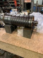
Got the spindle out today. Pretty easy. Heres some pics.

I moved the table out of the way and moved the spindle out all the way to the front in Y and all the way up to the limit. You need all the head space .

Drain the oil from the spindle housing and put the lines as high as you can to avoid siphoning from the tank.

Machined an aluminum pipe to about 6” length. Setup a long travel hydraulic jack under the spindle. Make sure you use a machined spacer. I also spread the load on the coolant tray with a 4 ft 8x8.

I used a square bar that was saw cut and the spindle was tilting on the way down at first till I changed to a machined bar.

Spindle weighs about 900 lbs > but wouldn’t drop under its own weight at first. I used a fine thread jack to jack against the upper casting roof to push the spindle down about 2”. It would then fall under its own weight.

Moved a forklift with a remote pendant into place and got a shorter spacer and lowered with the jack till I had 8” of the casting out.

Made a clamp out of 8” x 8” wood. Diameter of the casting is 6.9”.

Removed the jack and lowered the spindle all the way out with the forklift. You have to be careful to keep the motor wires from snagging. I just went a little at a time and kept checking.

Set the spindle on the table into the alu pipe. Moved the clamp up to the top and laid it over.
Im taking the top plate off tonight to look at the upper bearing. Hoping I can get away with just replacing that one.
 

Attachments

  • spindledmg.jpg
    spindledmg.jpg
    48.4 KB · Views: 247
  • spindle2.jpg
    spindle2.jpg
    44.8 KB · Views: 237
  • spindle3.jpg
    spindle3.jpg
    90.1 KB · Views: 281
  • spindle4.jpg
    spindle4.jpg
    92.4 KB · Views: 338
  • spindle5.jpg
    spindle5.jpg
    94.7 KB · Views: 215
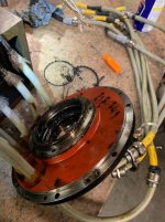
That’s a bad bearing! Phenolic turned to black paste. The lower spindle bearings are smooth so Im going to replace the top bearing only for now. I was able to buy 2 identical ********* 7011 E T P4S UL bearings for $325 on ebay. Saving one for when the rest of the bearings fail.

A few tips for disassembly.

I mounted the spindle on large v blocks centered it and scribed a line to realign the encoder gear so I don’t have to adjust orientation for tool change with the parameters.

The motor wire strain relief system wins my vote for one of the worst designs for repair. There are two rings inside the strain relief under the rubber grommet,shield is squeezed between these. Top ring is a press fit on the cable housing but my wires were pulled out past the edge and swelled from oil. You have to use a scribe to slip the casing back under the ring, then unscrew the next section of the fitting to pull the ring to the top, screw the fitting back in and slide the ring past the shield wires which were also stuffed under the ring. If youre not careful you can rip the wires out of the motor potting.

Also the motor temp wire strain relief fitting has to be removed. They crimped the wires after they pulled them through the rubber grommet so I snipped the rubber above each wire and pulled the wires out. (Put extra wire markers on the 4 wires before you do this as the factory ones can slip off).

The air blow rod comes out first, then there are threaded puller holes in the encoder ring to remove it with long M4 screws.
Te balancer ring is held in place with a setscrew. I pulled it with a gear puller. Remove the small keyway so it doesn’t get lost.

Remove the screws holding the bearing casing. Use long M4 screws in the threaded puller holes to remove.
There is a bearing shield that attached from the top with 4 allen screws. The shield kept debris from the bearing out of the motor.
I was able to pull the inner bearing race with a puller and a stepped spacer. If you don’t use a stepped spacer, youll pull the stator out to the edge of the spindle bellville shaft. The outer race came out with a slide hammer after the bearing casing was clamped in a milling vise.
 

Attachments

  • bearing.jpg
    bearing.jpg
    54.5 KB · Views: 200
  • bearing2.jpg
    bearing2.jpg
    57.1 KB · Views: 195
  • bearing3.jpg
    bearing3.jpg
    52.3 KB · Views: 186
  • bearing4.jpg
    bearing4.jpg
    86.9 KB · Views: 165
  • bearing5.jpg
    bearing5.jpg
    42.2 KB · Views: 162
I was able to get the new upper bearing in there and put it all back together. There is no preload to set on the top bearing. Its preload is set by a ring with a dozen springs set into pockets in it. These press on the outer race of the bearing and the outer race slides into position. Still a snug fit. I cooled the bearing on a tefc cooler and heated the housing. Tapped right in. Cooled the shaft and heated the bearing and the top case/bearing went on easy enough.

I wrapped the motor wires in lab seal tape and wire tied a bungee to pull the wires up when I pushed the spindle cartridge back in. Also a good idea to tape the motor wire shields to the cable as in the pic below so it doesnt get stuck under the strain reliefs.


Running it in now. Not heating up but with no preload to worry about, dont expect any problem there. However, even though I scribed the encoder gear in relation to the keyed balance ring, the M19 position for tool change is 90 degrees off???

I dont see any mention in the parameters of the constant that is connected with spindle orientation. Trying to get the procedure from DMG but not hopeful about that. If anyone knows how to reset spindle orientation on these millplus control machines please advise.
 

Attachments

  • bearing.jpg
    bearing.jpg
    88.3 KB · Views: 170
  • bearing2.jpg
    bearing2.jpg
    74.3 KB · Views: 126
  • wire.jpg
    wire.jpg
    83.8 KB · Views: 171
  • chill.jpg
    chill.jpg
    52.4 KB · Views: 129
So I did get a fast response from DMG after all. Heres the procedure to realign the spindle orientation.

Set middle rear switch in cabinet to the left. Change parameter 1036 to "1" Change parameter 2590 to "0"

Parameter 2414 spindle orientation can now be set. Mine was at 109000 and was about 90 degrees counterclockwise from where it should be which is aligned with the x axis and to the left.

Adding to that number moves M19 clockwise. After changing 2414 to ("125000" to start with for me) you have to change 2590 and then 1036 back to their original seetings. IF YOU DONT CHANGE 1036 AND 2590 AND CHANGE BACK, THE SPINDLE ORIENTATION WILL STAY THE SAME EVEN THOUGH THE NUMBER IN 2414 IS DIFFERENT.

Flip switch in cabinet to the right.

Reboot and flip the access switches so you can setup the machine with the door open (if you MDI m19 with the door closed you cant open the doors until you do an M3SXX or M4SXX.

Spindle orients and is locked. I used a .0001 indicator and swept the drive key. Took several cycles but I ended up at "206000" which brought the key to within .001 parallel to the x axis.

Tool change works again!! Still cant figure out why the orientation changed keeping the encoder gear at the scribed position. If anyone knows what might have happened there, Id appreciate an answer.

All in all pretty easy. Definitely worth saving the 7k-9k cost to send it out. I dont think the lower bearings would be that bad. Those are sealed bearings and are pretty cheap when they have come up on ebay, checking over the last year with terapeek.
 
I added a remote pendant to my crown walk behind straddle forklift. The blade tips stick out about 20” past the front wheels, enough to move them into the enclosure. I use that lift for these types of things.
 
That makes awesome sense. So it's a crane pendant or the like hooked into the forklift's control manifold, and it gives you this kind of function. Awesome idea. (I'd copy it but its above my skill level....)
 
I just put a mil connector on the control arm and wired it into the push button switches in the arm. You just need to use the type of pendant switch that only allows one switch to be pressed at a time.
 

Attachments

  • pendant.jpg
    pendant.jpg
    91.6 KB · Views: 134
That makes awesome sense. So it's a crane pendant or the like hooked into the forklift's control manifold, and it gives you this kind of function. Awesome idea. (I'd copy it but its above my skill level....)


I've had riggers in here with giant forklifts that are completely radio controlled. Pretty awesome to watch the guy walking around the lift/machine, checking clearance, adjusting on the fly, all while driving it with a massive remote control.
 
Sadly I think my forlifts are both controlled by levers directly controlling valves, so @markp's technique is probably not applicable to them. and I'm sure the rigger's forklifts @teachmeplease describes are beyond my reach...

But I can dream.... (:-) And maybe scheme....


Back
Top