Hi All!
I am new to this forum, and CNC forums in general, but as we picked up a FADAL 4020 this year for onesies-twosies it is seemingly a good resource for help as I have already found alot of helpful information for the machine on here.
Anyhow, I had a thread on a different forum regarding this but did not receive much response so I figured I would reach out here.
We were having a very periodic RS323 communication issue with a USBCNC box from the FADALCNC guys which we ended up assuming was due to a failing DC power supply. The DC PSU that was in the machine when we bought it was some retrofitted computer style PSU. Anyhow, on the recommendation from the CNCPRO FADAL techs we purchased a new original FADAL DC PSU from them, we received it and wired it into the machine, but we have an issue with supply voltage to the power supply (I assume the aftermarket PC style one we had before didn't care about the voltage as much).
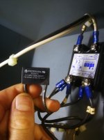
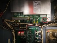
Anyhow, the pictures I am attaching will likely do a better job explaining whats going on than I will do here. I talked with a tech at FADALCNC and he said if we don't have the 110V into the DC PSU it will not kick on. I have verified every connection for all of the COM/+5V/+12V/-12V and our source for the AC in.
The AC in to our DC PSU is giving me 80VAC, this 80VAC is coming from the second pole of a solid state relay mounted above our CNC POWER button. This Pole is fed from an "electrocube" module that is coming off the other pole of this solid state relay. To my understanding this is the "brown out" circuit? The tech at FADALCNC said we should see the 110V at both lower poles of our solid state relay which are connected to either side of the CNC POWER button, and then the top two poles are to COMMON and +5V. All of this is correct except whatever this "electrocube" is doing, is creating 80VAC into the second pole of CNC POWER switch as well as 80VAC into our DC PSU.
I have sent these pictures to the tech at FADALCNC but have not heard back, I am wondering if anyone on here has some insight. Is that second pole of the CNC POWER button and the solid state relay supposed to have another 110V phase connected to it? We are a bit confused by how this power circuit is wired. I would imagine that only one pole into the switch should have 110V then when that is sent thru to the DC PSU by the CNC POWER button the PSU will supply the +5V to the coil of the relay and hold it on self powering the PSU...
Thanks for any help guys!!


