What's new
What's new

Fanuc OM spindle motor problem (no torque)

ToolCat

Aluminum
Joined
Dec 20, 2005
Location
Kearney, NE
Help.. I have a Makino RMC 55 with Fanuc Om. The spindle at low rpm has little/no torque. If the motor is set at 100rpm you can drag your finger on the spindle and stop it without much pressure. The motor will then make a couple high pitch beeps and will start back up if let go quick... but if it is held longer I can hear a relay or contact pop, requiring a reboot.
 
Is this a new to you machine, or a new problem on a machine you have run for years?

Either way, it would help if you would look at the spindle drive and see what the alarm that is created by stalling the spindle is.
The brand and model of the spindle drive and motor would be real useful too, since some MTB's used other than Fanuc drives and motors on their machines.

Bill
 
Recently purchased it from a tech school. mjk, I didn't see a torque curve in the manuals. I'm going through them again though.

It isn't creating an alarm when the spindle is stalled.

From what I read Makino had two spindles motors available; 45-4500rpm standard and an optional 60-6000rpm. I believe this one has the 6000rpm spindle because I noticed that is the rpm is printed on the Fanuc motor plate.

Here is a pic of the motor plate and one of the spindle drive.

IMG_3993.jpg

IMG_3994.jpg
 
Your spindle motor is a three phase induction motor with a controller that amounts to a fancy VFD with a feedback sensor. I believe it uses what Fanuc calls an M rpm sensor. I would check the sensor and its wiring. Also - I am surprised that you can run that motor at 100 rpm. 100 rpm may be outside the allowed range.
 
Thanks Bruce. I just now tried setting the spindle at 200rpm and turning it on/off and forward/reverse directions. I noticed if the spindle stops in a certain orientation it won't start but it will beep the high frequency sound while pegging the load meter until the relay or contact pops, requiring a reboot. I rebooted and when the spindle was in that location again while beeping I quickly spun the spindle by hand and it started.

I found an old thread with the below comment. I'll pull the fan and see how dirty the sensor and shaft are.

I think Viper has it.
I've had this problem on several machines as of late. All would exhibit the same symptoms. Jerky movement and pegged load meters. The cause in all cases was due to dirt accumulated on the end of the motor shaft where the speed sensor is. A careful cleaning and check of the gap between the sensor and the shaft cured every one. This sensor is under the fan cover. This may not be your problem but something to check.
Dan
 
Not surprised really

Our old bridgeports with Fanuc motors you could easily stop the spindle rotating at 50 rpm by hand and they were dead easy to stall when form
tapping 316 stainless( luckily the tap had more strength than the motor :))

That plate picture shows the truth, the 1500/6000 rpm is the ideal operating range of the motor, usually the range where it developes peak torque

Sure it will run slower or faster, but the torque curve really does drop away fast when you start going slower.

Boris
 
The fact that the spindle won't start in certain orientations suggests that your drive may not be functional on all three phases. Properly driven, a three phase motor has good starting torque in any orientation. I still would not rule out the sensor though....
 
Okay, things just went worse.
I pulled the fan and found the sensor and shaft. They were sealed and are clean.

I then marked the spindle with a pen so I could try starting it in various positions. I found the spot it wouldn't start up from. When it was trying to start I quickly spun the spindle by hand again but a fuse or something went. It won't take any mdi commands and so I shut it down and restarted. Still no good. It won't take any mdi commands. Any ideas? Is there a fuse for the spindle?


------------------
updated..few minutes later.
After letting it set for 15 minutes I turned it on again. It will now take mdi commands again, however the spindle is dead. When I give it a M3 the load meter maxes out for a few seconds and then something pops.. from that point it won't take mdi commands until rebooting.
 
I don't know your machine, I have a Kitamura with a 0M. I would look for fuses anywhere in the machine. Might not be in the spindle drive - but look there as well.
 
So the critical question is: where is "I can hear a relay or contact pop" and "and then something pops" coming from?
The electrical cabinet on the right side and back OR the 2 flexable wireways on the left side and back?

I have had quite a few broken wires in the flexable wire ducts over the years.
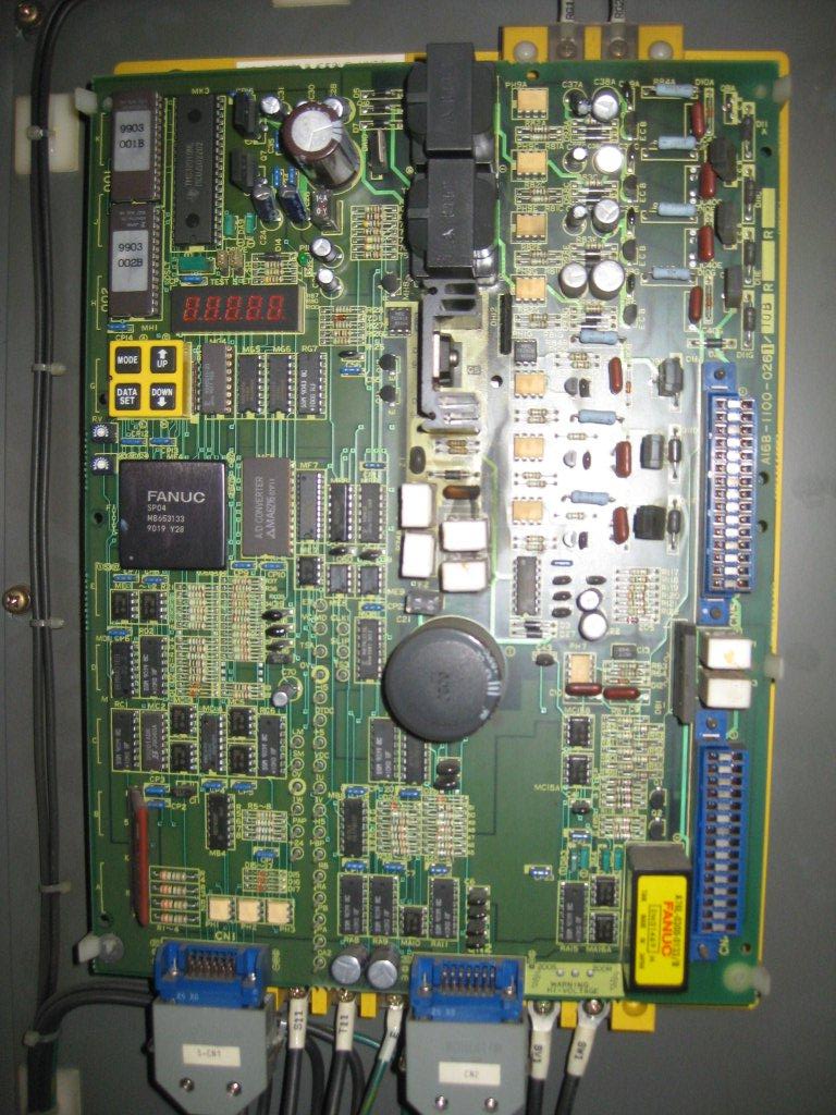
An easy way to check is removing the 3 wires on the lower right of your spindle amp (su1,sv1,sw1) and checking resistance betwen each pair (3 checks) all should be well below 1 ohm. This test works best if the axis are in a position like your edit in your last post where the spindle is "dead". If you move the axis, the broken ends may reconnect and show good on the test, and it will run sort of...
In the case I have described above, the "pop" is arcing at the point the wires are broken, or at the point that the insulation is broken and arcing to ground. This happening on a repeated basis may cause problems in the drive, that will give a hard alarm that will not clear.

If you are rehoming the machine at power on, after cycling power because of the "pop" and sometimes it will run again. The movement you are doing may be enough to reconnect the broken ends of the wire(s).

Normally the 5 digit display on the spindle amp would have some display after the "pop".

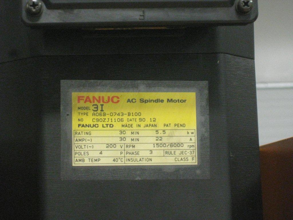
"From what I read Makino had two spindles motors available; 45-4500rpm standard and an optional 60-6000rpm." This may only be a change in the pulleys on the motor and spindle and both using the same motor. There will be parameters that differ also.

Bill
 
The motor windings read 4.5ohms across the leads.

The pop sounds like solenoid contacts. I had someone push the cycle button to a mdi m3 command while I was listening with the cabinet open. I still can find where it is coming from but sounds like it is behind the spindle drive board. Is there a solid on the 2nd drive board behind the front of the main drive board?

Did discover the alarm code on the spindle board. It is displaying 02 after pop.

Alarm 02 (AL-02) Excessive Speed Deviation
Causes
Overload, transistor module is damaged, loose connections, error with speed feedback signal, blown fuse.
Remedy
Replace parts, check connections, review cutting conditions.


I am currently thinking something burned out on the drive board. I noticed something this evening while looking at the spindle drive board. There are four larger transistors in the upper right hand corner of the board. The top one is missing/broken off. You can even see it missing if you look careful in the above photograph. Who know how long it has been running that way at the school. Wish I would have seen this before I messed with the low speed starting of the motor.
 
I don't know about the missing device - might not be needed. Can you tell if the PCB spot was ever populated? The board you are showing is nothing like my spindle drive. Mine looks like this:

Fanuc Alpha spindle drives, Series a06b-6078, Repair, Exchange or NEW

My machine has a power supply, spindle and servo drives located so that the heat sinks at the back of the drive are in an air tunnel. The drives are all powered by the power supply and face out.
 
There must be a transistor missing because I can see the broken leads where it was soldered on the board.

The photo is of the of the outside board. Mine has the heat sinks that fit into an air tunnel that is part of the cabinet too. This one has a part number of
A06B-6060-H003
 
If I mdi: s100 m3 and then by hand turn the spindle continually the best I can it won't pop out. The load meter even comes down while spinning by hand. A few seconds after I stop it pops and gives the 02 alarm on the drive board. (the pop is coming from the drive board) Therefore the sensor on the spindle is must be ok, and the problem must be something on the drive or I'm missing a fuse or breaker. I can measure 200 volts coming to the board but it isn't making out to the spindle.
 
Power for the spindle motor should come directly from the drive - not the board you have photographed. The voltage/frequency will depend on the speed you set. A setting of 200 rpm will give a low voltage and frequency to the motor. Why are you using such a low rpm setting?
 
I'm using the low speed for testing, because the spindle was hesitating starting. Now I'm using it because if I want to test if the sensor is the trouble since the alarm is Alarm 02 (AL-02) "Excessive Speed Deviation". Again turning it by hand after giving it a m3 will prevent the relay from popping because the sensor sees the spindle turning, which I would think means the sensor is working and the problem is something is fried on the board. The board for the motor is behind the spindle brains board the picture is of. I can pull the top board and photograph the drive board under it.

So the question is which component on the drive board is the problem. According to alarm 02 it can be the "transistor module". 200V is coming to the board but nothing is making it out of the board to power the motor. The choices of the problem from the book for alarm 02 are: "Overload, transistor module is damaged, loose connections, error with speed feedback signal, blown fuse." I wonder which components/module they mean "transistor module". Would this be the whole drive board?
 
The spindle drive (the picture I linked) has a finned heat sink sticking out the backside. That heat sink is for the semiconductor devices (not sure which type in your module) that power the spindle. The devices are inside the drive. If you remove the drive - the side panels are easily removed - you can do a visual check for obvious damage. I am guessing these are the devices that constitute the "transistor module". BTW, the wires that power the motor are attached to the front of the drive.

I may not have understood what you have written, but does the motor move on its own at all (with hand start)? I understood yes, but that may be wrong. If yes, why do you say that there is no power to the motor?
 
That is correct. The spindle does not move on it's own. I tested again today with someone standing behind to watch the readout on the control board. When I mdi s100 m3 and spin the motor the readout is displaying the speed of the spindle and as soon as I stop the relay on the driver board pops and gives the 02 alarm.

I've been emailing with fanuc this morning. They are very helpful and quick with replies. I have the two boards removed and tested the capacitor module with an ohm meter. It does appear burned out.
 
The fact that the spindle won't start in certain orientations suggests that your drive may not be functional on all three phases. Properly driven, a three phase motor has good starting torque in any orientation. I still would not rule out the sensor though....

The picture of the board IS a spindle drive, predates the Alpha series link you posted. I have a '94 0TC and the spindle drive/board is just about identical to the OP's picture. Only cost $5500.00 when it blew up 2 years ago.


Back
Top