What's new
What's new

G76 threading

Stevenhitt

Plastic
Joined
Aug 13, 2018
This is what I have guys. Hardinge lathe 1991 OT Fanuc controller

Thread tool touch OD of 3/8 stock at 4.425 I have program as follows.

GO X4.525:
G76 P010260 Q0015 R0.001:
G76 X4.375 Z0.7 R0 P0360 Q0100 F0.0625

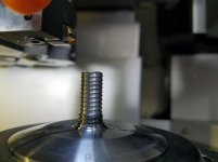
If I change the x values and chase the thread on a piece of 3/4 stock it works great.
When I change to 3/8 stock I keep the draw back on x to 100 above stock the threads
look like ski slopes lol?
one side of thread looks like 30 degree the other side looks like 60 degree from center out.
What am I doing wrong. Just got this machine in off of ebay lol ... HELP! Thanks
 
As for your threads looking like a ski slope, what tool are you using to cut the threads?
Can you share a picture of the threads and tool?
 
It's almost as if the infeed angle is backwards.
Grab a setup piece of stock and change P010260 (which actually looks fine) to P010230.

Or your parameters are wonky.
 
It is a 1991 Hardinge Conquest 42 (lathe)
It currently has x spindle center line of 4.o X

See this is what stands out here as odd.
I haven't ran a Fanuc lathe in a LONG time but did for 15 years. And I've never seen X0 be 4".
It's like you have scaling in effect or something. Someone with more Fanuc knowledge than me should be able to spot your issue right away.
Sinha, Angel, etc... There are a lot of people on here way way smarter than I am ;)
 
I'm no expert at this, but if the centerline is at X4.0, wouldn't you touch off 3/8 stock at 4.375 in Diameter, or 4.1875 in Radius?

Also, why are you starting the threading routine at X4.525, if you are touching off at 4.425?

This is what I have guys. Hardinge lathe 1991 OT Fanuc controller

Thread tool touch OD of 3/8 stock at 4.425 I have program as follows.

GO X4.525:
G76 P010260 Q0015 R0.001:
G76 X4.375 Z0.7 R0 P0360 Q0100 F0.0625

If I change the x values and chase the thread on a piece of 3/4 stock it works great.
When I change to 3/8 stock I keep the draw back on x to 100 above stock the threads
look like ski slopes lol?
one side of thread looks like 30 degree the other side looks like 60 degree from center out.
What am I doing wrong. Just got this machine in off of ebay lol ... HELP! Thanks

Hello Steven,
That's got to be one of the most convoluted way to program a Thread I've seen in a long time. Why would you not use coordinates in your program that actually relate to the Tread you're cutting. I assume you're a one man show, the programmer and operator of the machine and therefore, you know what's going on, but no one else would be able to identify the Thread you're cutting by reading the Program.

Based on your numbers in the Program example (X4.375, P0360 and Q0100), the first pass of the Threading Cycle will be at X4.427; a fresh air cut when the tool touches the workpiece at 4.425.

The Thread Angle Specified is correct. 30degs is not an available option for your control (29degs is available), so that can't be the issue. However, specifying an angle less than the actual included angle of the Threading tool only results in the trailing edge of the insert doing some of the cutting; the Thread form is determined by the profile of the Threading Insert.

Except that you have posted the picture and specification of the Tool, the most obvious cause would be the Thread Form of the Threading Insert. The program, although very clumsy in its definition, should work. The only other thing that will have changed is the Helix Angle of the Thread, given the different OD, but consistent Thread Lead.

Regards,

Bill
 
I think the OP does not understand geometry offsets and or setting a part origin. Seems like he is working the machine coordinate system.

Is the tool on center? As you get smaller on part diameter, problems with the tool being off center become greater.
 
Hello Steven,
That's got to be one of the most convoluted way to program a Thread I've seen in a long time. Why would you not use coordinates in your program that actually relate to the Tread you're cutting. I assume you're a one man show, the programmer and operator of the machine and therefore, you know what's going on, but no one else would be able to identify the Thread you're cutting by reading the Program.

Based on your numbers in the Program example (X4.375, P0360 and Q0100), the first pass of the Threading Cycle will be at X4.427; a fresh air cut when the tool touches the workpiece at 4.425.

The Thread Angle Specified is correct. 30degs is not an available option for your control (29degs is available), so that can't be the issue. However, specifying an angle less than the actual included angle of the Threading tool only results in the trailing edge of the insert doing some of the cutting; the Thread form is determined by the profile of the Threading Insert.

Except that you have posted the picture and specification of the Tool, the most obvious cause would be the Thread Form of the Threading Insert. The program, although very clumsy in its definition, should work. The only other thing that will have changed is the Helix Angle of the Thread, given the different OD, but consistent Thread Lead.

Regards,

Bill
Bill could it also be he might be using g96? if his tools are that far off in x location with his program g96 I would think could possibly cause that problem???
 
Bill could it also be he might be using g96? if his tools are that far off in x location with his program g96 I would think could possibly cause that problem???

Varying the RPM alters the start index of the Thread Lead, but the variation of Revs would be base on the current cut diameter, not the fact that the specified Thread Diameter in the G76 Block is way different to the actual diameter being cut. Accordingly, the RPM would be calculated on a diameter variation of only 0.052". There would possibly be a bit of Spindle acceleration involved moving in Rapid from the X Start position to the X cut diameter, which may cause a Thread Lead error at the Start of the Thread until the correct RPM for the diameter was achieved. If the Revs are doubled, or halved, the Thread Start will be indexed 180deg (half the Lead of the Thread).

It is possible that the error could be caused by RPM variation, but I don't think the RPM would vary enough to result in an error as great as the OP's.


Regards,

Bill
 
This is a peculiar problem.
1. G97 must be used
2. Try lower rpm
3. Try P----00 (what profile do you get?)
4. Does G92 also have the same problem?


Back
Top