What's new
What's new

G92 lathe threading cycle infeed strategy?

Jvizzi

Aluminum
Joined
Jun 15, 2011
Location
Florida
I almost never use G92, always G76 because you have so much more control over the details of the cycle. However, Fusion 360 does not seem to have any support as of yet for posting G76 thread cycles. The only options you have are "Cycle" which outputs a G92, and longhand, which posts out each and every pass (infeed, cut, exit, retract) with G32.

However, it does still allow you to select an infeed angle with the G92 cycle, other than just 0 degrees (straight radial plunge infeed). For example, when I select a 30 degree infeed, I get this code:

N109(THREAD 3/4-20 2A)
T1515 (LAYDOWN, 16ER 20UNF)
G54
G97 S1500 M03
G00 X0.95 Z1.
M08
Z0.1632
G92 X0.7458 Z-1.0968 F0.05
X0.7417 Z-1.098
X0.7375 Z-1.0992
X0.7333 Z-1.1004
X0.7292 Z-1.1016
X0.725 Z-1.1028
X0.7208 Z-1.104
X0.7167 Z-1.1052
X0.7125 Z-1.1064
X0.7083 Z-1.1076
X0.7042 Z-1.1088
X0.7 Z-1.11
G00 X0.95 Z1.
M09
G00 G28 U0. W0.
T1500
M01

As you can see, the Z depth of each pass increases slightly, along with the X. My question is, would this actually work? Can you actually do this with G92 cycle? If you trig out the difference from one pass to the next, you do get about 30.3 degrees.
 
Fanuc G92 always uses straight plunge.
You will see the difference only at the end of the thread in this program.

Even if you are using a CAM, you can always manually edit the program to have G76.
 
Hi Jvizzi:
Sinha wrote:
"Even if you are using a CAM, you can always manually edit the program to have G76."

I agree 100%.
The G76 cycle is so much more efficient and so much easier to edit, that I wouldn't even consider running the crap code that Fusion (and HSMWorks) puts out.
If I need better control of each pass I prefer G33 over G92; otherwise it's G76 for me.

Cheers

Marcus
Implant Mechanix • Design & Innovation > HOME
www.vancouverwireedm.com


I almost never use G92, always G76 because you have so much

hy Jvizzi :) i am not a Fanuc guy, but i think that G76 targets a cycle, while G92 targets single syncro passes :) if i got this wrong, than please ignore my answer :)

most applications work with default_threading_cycle, while particular cases do not work

a default_threading_cycle may allow many inputs, but in the end, cnc_control is in control, and not the programmer ... this means that is hard to get full control on a default_threading_cycle, but not impossible

single_syncro_pass code ( G92 ) is there to deliver full control

thus, full control is possible with bought codes, but should be easier with G92

full control = depth and infeed patern :)

would this actually work?

give it a try :) try to cut 2 intercalated spirals

Code:
[COLOR=#333333]    G00 X0.95   Z+1[/COLOR]
[COLOR=#333333]    G92 X0.7458 Z-1.0968    F... G95
[/COLOR][COLOR=#333333]    G00 X0.95   Z[/COLOR][COLOR=#333333]+[/COLOR][COLOR=#333333]1[/COLOR][COLOR=#333333]+pitch/2[/COLOR][COLOR=#333333]
[/COLOR][COLOR=#333333]    G92 X0.7458 Z-1.0968    [/COLOR][COLOR=#333333]F... G95[/COLOR]
or
Code:
[COLOR=#333333]    G00 X0.95   Z+1
[/COLOR][COLOR=#333333]    G92 X0.7458 Z-1.0968 F... G95 C0
[/COLOR][COLOR=#333333]        X0.7458 Z-1.0968          C180[/COLOR]

results should be sugestive for what this code can do :)
 
there is :

position_before
G92 position_after F... G95

if infeed is among an angle, thus not straight down, than at least one position will have a variable Z

position_before with variable Z should be critical
position_after with variable Z may be relative
... if there is a groove at the end of the thread, and this groove is wider than the pitch, and machine is always finishing each pass inside this groove ( including long run deviations, etc ), than final Z may be constant or variable
... if there is no groove at the end, and also no lead out ( no tapered ) movement, it means that tool is finishing cutting inside the material; at this point an issue appears : when you use constant Z into position_after, you may put the tool to a lot of stress when it almost finished; to help it, you must somehow control the final_section of the cut; in other words, you will get your thread, but at the end you will stress the tool; avoiding this involves a good responsive control, understanding how the control behaves for such codes, and customizing infeed program, so to help the tool

this effect may occur, but also tool life may be found reasonable, thus there may be no reason to adjust it :)

ideal is to customize the code generator to avoid this when creating code ... kindly !
 
Fanuc G92 always uses straight plunge.
You will see the difference only at the end of the thread in this program.

Even if you are using a CAM, you can always manually edit the program to have G76.

Yes, except Fanuc ( in case of threading ) is dumber than a box of rocks.

On a Haas control, I use G76 for the main portion of the thread, then I chase the OD to remove the burrs, and then I use G92 for 1 or 2 spring passes on the thread.
Unfortunately on a Fanuc that's just isn't possible.
You either use G76 for main and chase, or left with G92 for both.

So, as it stands... Whenever I have a bitch of a thread on a bitch of a material, I use G92 on both controls and it's all coded longhand.
 
On a Haas control, I use G76 for the main portion of the thread, then I chase the OD to remove the burrs, and then I use G92 for 1 or 2 spring passes on the thread.
Unfortunately on a Fanuc that's just isn't possible.
It is possible on Fanuc also.
One only needs to shift the start Z of G92 by the Z-shift amount between the first and the last helix of G76.
Shift in G92 start-Z would be [a x tan (half of tool-tip angle)] where
a = [Depth of thread - First DOC - Finishing allowance/2]
I have not tested it, but I think it is mathematically correct. Let Bill confirm (as always).

Unacceptable argument.
If both cycles start @ say .1 from the face and they both have the same pitch and X-minor, they both need to figure out
the math from-to on their own for each depth, and they both should arrive at the same conclusion.
 
I'll use G76 to start with, that way we can adjust it at the machine easily if we need to. Then if there is a burr, I'll change the CAM output to G32 and repost it. Then you can just copy the the last pass for the tool to follow. So I can turn, thread, return the front and back chamfers, then rerun the last thread pass.

I've never like G92 with the straight infeed. Did G92 develop in between G32 and G76 cycles, so that there really isn't much use for it? I know some people prefer it....

I like it for rotary shoulder connections because I like to take the same DOC for each pass until the last 3 passes.
 
Unacceptable argument.
If both cycles start @ say .1 from the face and they both have the same pitch and X-minor, they both need to figure out
the math from-to on their own for each depth, and they both should arrive at the same conclusion.

It is not argument.
It is maths, based on the following considerations:
G92 has straight plunge. Threading helices do not shift in subsequent passes.
The first roughing pass of G76 also has straight plunge. But, it is not the final thread position.
The last roughing pass of G76 is the final thread position. Finishing passes do not shift.
Therefore, all we need to know is the shift between the first and the last roughing pass of G76.
The start-Z of G92 would need to be shifted to the left (for right-to-left threading) of the start-Z of G76 by this amount, because all threading cycles start cutting at the same marker pulse. The formula for the shift amount is given in my previous post.

But, as I said, I have not tested it, though I believe, it should work, unless my understanding of the behavior of G76 is not exactly correct.
Please give it a try. At the most you would scrap one piece. If it works, you may find it very useful. CAM also does similar calculations. As reported by Brian, he can turn, thread (G76), re-turn, and re-thread (G32).

Edit: The underlined statement is not correct. The first roughing pass also has a Z-shift. Consequently, the formula given by me in my previous post would slightly change (the First DOC term would not be there).
 
Last edited:
Did G92 develop in between G32 and G76 cycles, so that there really isn't much use for it?

Broadly speaking, G92 is G32 only, with three additional moves added to it. (There are, of course, other differences also)
G92 vs G32 is somewhat like G90 vs G01.
 
It is not argument.
It is maths, based on the following considerations:
G92 has straight plunge. Threading helices do not shift in subsequent passes.

BS!
No straight plunge on a thread or it will never be correct!

Somehow Haas figured it out a bit over 20 years ago. Nowadays it just might be high time for Fanuc to do the same!
Finish pass from Start-End in X and Z should always be in the very same position regardless G76 or G92 otherwise the thread is fucked up!

In what manner are the Haas Threading cycles different to the Fanuc? Following are extracts from the Haas programming Manual with the corresponding extract from a Fanuc Manual.

From Haas Manual
G92 Threading Cycle

F(E) Feed rate, the lead of the thread
I Optional distance and direction of X axis taper, radius
Q Start Thread Angle
U X-axis incremental distance to target, diameter
W Z-axis incremental distance to target
X X-axis absolute location of target
Z Z-axis absolute location of target

Chamfering on retract at the End of Thread can be set with Settings 95 and Setting 96. Chamfering is turned On/Off with M23 and M34 respectively.


From Fanuc Manual
G92 Threading Cycle

G92X(U)__ Z(W)__ R__ F__ ; Lead (L) is specified.
X Absolute X-axis target value
Z Absolute Z-axis target value
U Incremental X-axis target distance - diameter
W Incremental Z-axis target distance
R Distance and direction of X axis taper - radius value
Q Start Thread Angle – Describes Start Angle for Multi Lead Threads
F Feed rate

Chamfering distance is specified in a range from 0.1L
to 12.7L in 0.1L increments by parameter (parameter number is control model specific but parameter 5130 applies for controls from around FS15 on)

From Haas Manual
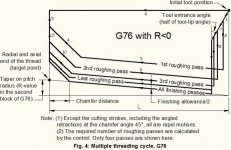
G76 Threading Cycle, Multiple Pass

A Tool nose angle (value: 0 to 120 degrees) Do not use a decimal point
D First pass cutting depth
F(E) Feed rate, the lead of the thread
I Thread taper amount, radius measure
K Thread height, defi nes thread depth, radius measure
P Thread Cutting Method P1-P4
Q Thread Start Angle (Do not use a decimal point)
U X-axis incremental distance, start to maximum thread Depth Diameter
W Z-axis incremental distance, start to maximum thread length
X X-axis absolute location, maximum thread Depth Diameter
Z Z-axis absolute location, maximum thread length

Chamfering on retract at the End of Thread can be set with Settings 95 and Setting 96. Chamfering is turned On/Off with M23 and M34 respectively.

Fanuc Two Block Cycle, referred to as FS16 Standard Format

G76P (m) (r) (a) Q (d min) R(d);
G76X (u) _ Z(W) _ R(i) P(k) Q(d) F(L) ;
m = Repetitive count in finishing (1 to 99)
r = Chamfering amount
a = Angle of tool tip
One of six kinds of angle, 80°, 60°, 55°, 30°, 29°, and 0°, can be selected,
and specified by 2–digit number.

Q (d min) = Minimum cutting depth (specified by the radius value)
R(d) = Finishing allowance
R(i) = Difference of thread radius radius If i = 0, ordinary straight thread cutting can be made.
If i is omitted I = 0 is assumed

P(k) = Height of thread. This value is specified by the radius value.
Q(d) = Depth of cut in 1st cut (radius value)
L = Lead of thread (same as G32).

Fanuc controls that use FS16 Standard Format can also be set via parameter to use Single Block Multi-repetitive Cycles, referred to as FS15 Format. The exception to this is the circa late 80’s FSO control.

The Fanuc Single Block G76 (FS15 Format) is the same as the Haas G76 cycle.

Unless the Haas G92 Cycle has been changed in recent time and I’ve not become aware of it, this cycle has no function to specify a Thread Profile Angle (Tool Tip Angle) and therefore, each successive cut will be made by the tool advancing in the X axis only. With the Haas (and Fanuc) G76 cycle, a Tool Tip Angle can be specified to have the tool cut with the Leading Edge of the insert.

There are two ways in which the Specified angle can be applied:
1. By calculation a minute shift in the Z Start Point (same method described by Sinha)

2. By applying an Index Angle for each Thread Pass. This in essence is cutting a Multi-lead Thread where the Thread Pitch is equal to amount of shift required to have the Trailing Edge of the Threading tool just kiss the Trailing Thread Flank.

In either case, the position of the Thread Groove relative to the original Z Start will be shifting as the Threading Process continues.

The Fanuc control performs a shift of the Z Start with each Thread Pass if a Tip Angle other than Zero is specified. If you observe the movement of the tool closely at the start of each Thread Pass, you will see this happen. However, the tool always returns to the original Z Start coordinate at the end of each Thread Pass.

The above being so, the only way I can see a G92 Threading Cycle being able to track precisely in the Thread Groove previously cut using a G76 Cycle and where a Tool Tip Angle other than Zero was specified, is if the Tool didn’t return to the original Z Start coordinate, but to a coordinate that equates to the shift required to have the Leading Edge of the Tool cut in accordance with the Tool Tip Angle specified.

I’m unsure if the Haas returns to the original Z Start Coordinate after every Thread Pass. If it were the case that it returned to the Offset Z Start and the G92 cycle was executed immediately from the Offset Z Start, then I can see that the Tool will track the last Threading Pass made by the G76 cycle. However, if the original Z Start for the G76 Cycle with a Tool Tip angle specified was, say, Z10.0 (mm) and a G92 Cycle was subsequently executed from the same Z Start, I fail to see how it would track precisely in the same Thread Groove as the G76 Cycle's final pass.

A very simple method to take further passes at finish DOC on a Thread cut using the G76 cycle, is to execute another G76 Cycle with the First Threading Pass value the same as the Thread Height specified in the cycle. All other parameters of the Thread should not be changed. This will result in a single threading pass at full depth and will precisely track the Thread Groove previously cut with the G76 Cycle.

Regards,

Bill
 
i am not sure what SeymourDumore is refering to ...

... my guess would be targeting forces on a single edge, instead of both edges of the insert

... 2nd guess would be a syncro error that is not visible at big depths, but only at small passes, and it may be overcomed by shifting Z with specific amounts or using depths greater than whatever limit ... it may be possible, but does not sound plausible :)

i really have no clue :)
 
It is possible on Fanuc also.
One only needs to shift the start Z of G92 by the Z-shift amount between the first and the last helix of G76.
Shift in G92 start-Z would be [a x tan (half of tool-tip angle)] where
a = [Depth of thread - First DOC - Finishing allowance/2]
I have not tested it, but I think it is mathematically correct. Let Bill confirm (as always).

This formula is incorrect. Since the first roughing pass also shows a Z-shift, the correct formula is
a = [Depth of thread - Finishing allowance/2]
 

Attachments

  • Fig. 4.jpg
    Fig. 4.jpg
    58.3 KB · Views: 3,041
A very simple method to take further passes at finish DOC on a Thread cut using the G76 cycle, is to execute another G76 Cycle with the First Threading Pass value the same as the Thread Height specified in the cycle. All other parameters of the Thread should not be changed. This will result in a single threading pass at full depth and will precisely track the Thread Groove previously cut with the G76 Cycle.

This is THE solution, simpler than the simplest!


Back
Top