What's new
What's new

Hardinge VMC700 internal communications problem

Leadfootin

Cast Iron
Joined
Feb 5, 2009
Location
London
Working on a VMC700 in the Windsor, Ontario area which had the Fanuc main controller replaced after delivery with an empty slot! It seems the PLC which reads all the various position and alarm sensors is not communicating with it. Main safety circuit is intact after a couple switch adjustments and you now have to verify door switches on start up.
Another tech had jimmied the door switches and caused numerous errors delaying me getting to this point. As well it appears the processor is not talking to the X,Y,X axis amplifiers as well as the spindle drive since all show a not ready condition. FWIW the processor communicates just fine with the control panel and CRT.

Is there a tech in the Windsor area who has both the knowledge and the required software to get this machine up and running?

Thanks,
Peter
 
Has anyone experienced similar problems or had to replace the PSU processor board? At this point I need some guidance to get this unit functional.
 
I don't know which board, but I think that I had to replace a com (daughter?) board on the 18i once.
I don't recall, but I likely diagnosed with phone tech help from Tennessee Industrial Electronics.
And they would have been where I got the part(s) as well.


-------------------------

Think Snow Eh!
Ox
 
In your other thread covering the same problem, I tried to tell you that the PSU B1 board you have is just a power supply it is not a processor (There may be an MCU on it for monitoring its own functions, but it is not a system processor). The slot that your picture shows open is usually just covered up with a simple plate when the PSU B1 is spec'd. If your machine was fitted with a PSU C then the slot is used because PSU C contains I/O functions.

If you doubt this, please look at section 2.1 through 2.3 of the Fanuc 18M maintenance manual. It pretty clearly shows the control structure and slot layout as well as that the servo system and I/O are all handled by the main board. Section 2.5.1 includes a block diagram of PSU B1 and again clearly shows that it is just a power supply.

The main board (module in slot marked 1 and labeled MAIN) contains the main board and a bunch of daughterboards that support the control functions.

When you first turn power on all 4 status LEDs should light for a moment. Then as the boot process occurs the status LEDs will blink on and off in a pattern until the the boot is complete at which time the leftmost status LED should remain lit. If it hangs during the boot you need to record the last pattern of status LEDs and reference the table in section 2.5.2 to determine the last boot sequence that finished. The next boot function will be the starting point for troubleshooting.

The unit is booting up correctly and I am referring to the left board in the PSU. There is a communications problem between the processor board which I am told has been replaced and the PLC in the upper right corner of the control panel. This results in a drives not ready state and inability to move any part of the machine. Most likely it is a software issue, probably in the processor board. I do not have the equipment to directly connect to the processor to determine the exact problem.
 
The unit is booting up correctly and I am referring to the left board in the PSU. There is a communications problem between the processor board which I am told has been replaced and the PLC in the upper right corner of the control panel.......

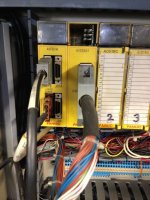
Post a picture of the " PLC in the upper right corner of the control panel". That way we can get the correct ID on the device. Fanuc does not use the term PLC in their controls.

The portion of the control that The processor board is the board marked MAIN in the card rack. The PMC (Fanuc speak for what most machines call a PLC) is a daughterboard of the main board and should be in slot 4 of the MAIN board. The PMC connects to the operator panel and I/O via the IOLINK connection on the front of the MAIN board.
 
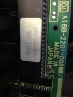
Will take photos of PLC next time I am there. Will pull board inlet side of PSU with all IO cables and get photos as well.
 
RIP memory contents, we hardly knew ya.

Thats the IO unit, not a PLC. The PLC functions are inside the control. It is referred to as the PMC. (see post#6)Only half-breed machines from the 70s &80s had separate PLCs. Or new machines from Europe I suppose.

Did this come from a dealer? sight unseen?
 
This thing was an auction purchase and came with a couple boards missing (he got shafted by either the auction house or the guy who sent it there). I was called in after numerous people "tried" to fix it by replacing IO boards, motor drives and the like without delving into the problem. As it stands I have now advised the owner to spend the money and have Fanuc service reps come and determine what is missing and or incorrect to cause the communications issues within the unit. If not some one will buy a very nice machine very cheaply.


Back
Top