What's new
What's new

Helical milling program

Parabellum

Plastic
Joined
May 25, 2019
Can anyone give me an example of programming say a 2" hole X 2.5" deep using a 1" cutter on Fanuc "OM"? I have been reading on this but my manual is not very specific. Is the best route Helical or should I concentrate on a "While/DO" program?

Thanks Much!
Parabellum
 
Nah,
Use a sub.
So something like this...

MAIN
(Assuming all is good at the top of the program)
G00 X0.0 Y0.0
Z1.0
G01 Z0.5 F2000 (I AM ALL METRIC)
G91 X0.5 F2000 (ALSO FOR PROCESSING REASONS, OR ELSE GENERALLY THE G91 IS IN THE SUB)
P1508100 M98 (SO READ PROGRAM 8100 150 TIMES)
G03 I-0.5 (FINISH ONE LAST REVOLUTION)
G90 (BACK TO INCREMENTAL)
G01 X0.0 Y0.0 (OR ALTERNATIVELY AN ARC OUT)
BLA BLA BLA


SUB
O8100 G03 I-0.5 Z-0.5 F1000 (MAKE SURE THAT THIS IS ON THE SAME LINE AS YOUR PROGRAM NUMBER, MAKES PROCESSING EASIER AND YOU WONT NOTICE THE SMALL STOPS BETWEEN RAMPS)
M99
 
SUB
O8100 G03 I-0.5 Z-0.5 F1000 (MAKE SURE THAT THIS IS ON THE SAME LINE AS YOUR PROGRAM NUMBER, MAKES PROCESSING EASIER AND YOU WONT NOTICE THE SMALL STOPS BETWEEN RAMPS)
M99


Not doing what you've suggested I could notice a small pause between sub iterations. I will give this a try.

Thanks!
 
O.K. I tried this out but, when the machine went to read the subprogram call line it gives a 08 P/S alarm...any thoughts?
 
Not used to actual Fanuc controls yet(have a Fadal with 18i-MB coming though), but what I'm used to is only the sub(N line number) or main(O*****) program number after the P and an L for number of loops if more than 1 .

SO,,
PO8100 L150

but that's on Haas's though.

.
 
Hello Parabellum,

The issue I have with using a Subprogram and repeating it a number of times, is that you must make sure that the Lead of the Helix is compatible with the Z full depth and the number of time the Subprogram is repeated. Further, as arguments can't be passed to a Subprogram, unless you were to register these values in Common Variables,you would have to edit the Subprogram for each different Z Depth, Helix Lead, Cutter Diameter and Diameter of Helix.

My option would be to create a Helical Milling Macro Program and call it with a Custom G Code. Following is a typical Call Block for such a Macro

G00 G90 G54 X0.0 Y0.0
G43 Z0.5 H01 M08
G103 Z-2.5 W-0.040 R0.04 I2.0 D1.0 V0.020 F15.0
---------------
---------------
Remainder of Program
---------------
---------------
M30
%

Where:
103 = The number registered to create a Custom G Code
Z = Z Absolute Full Depth Coordinate
W = Direction and Lead of Helix
R = R Plane
I = Diameter of Helix
D = Diameter of Cutter
V = Z Start Coordinate
F = Cut Feed Rate

Following is an example of a Macro for Helical Milling. This is a bare bones example with minimal Error Trapping. This program could be easily expanded so as to use a Tool Radius registered in an Offset Registry. You could have the program use Cutter Radius Compensation without actually using G41/G42 in the Macro. Instead of passing the diameter of the tool as an argument, the Offset Number would be passed and the value stored therein retrieved within the Macro Program.


Code:
O9010
(ERROR TAPS GO HERE)
IF[[#4 = #0] OR [#7 = #0] OR [#9 = #0] OR [#18 = #0] OR [#22 = #0] OR [#23 = #0] OR [#26 = #0]] GOTO900

G31 (or G53) (HALT BUFFERING)
#100 = #4003 (STORE GROUP 3 G CODE)
#1 = #5041 (GET CURRENT X POSITION)
#3 = #5043 (GET CURRENT Z POSITION)

#4 = [ #4/2  -  #7/2] (GET RADIAL MOVE OF CUTTER)
G90 G00 Z#18 (RAPID TO R PLANE)
G01 Z#22 F50.0 (MOVE TO Z START)
G01 X[#1 + #4] (MOVE TO CIRCUMFERENCE OF HELICAL PATH)

WHILE [#22 GT #26] DO1
#22 = #22 + #23
IF [#22 LT #26]TH #22=#26 (STOP OVER CUT IN Z)
G03 I-#4 Z#22 F#9
END 1
G03 I-#4 (CLEAN CUT AT FULL DEPTH)
G01 X#1 (RETURN TO CENTRE OF HELIX)
G00 Z#3 (RETURN TO INITIAL LEVEL)
GOTO901
N900
#3000 = 1 (MISSING REQ DATA - FIX)
N901
G#100 (RESTORE GROUP 3 G CODE)
M99
%

The above program allows for the Lead of the Helix to be changed without any thought of the number of time the Helical command must be repeated and whether the full Z Depth will be reached, or passed.

I have not tested the above code, but I can't see any obvious errors. Tread carefully if you use the code.

Regards,

Bill
 
Well your suggestion worked but the controller only ran the sub once instead of the 150 times per the code listed.... try, try .try!
Thanks for the response!

It should repeat 150 times on a Fanuc (M98 P1508100).

The L method also works on Fanuc. The advantage is that up to 9999 repetitions can be programmed.
 
Old Brain, New Info

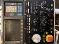
O.K. Guys, I appreciate all of the input. You are all great, but I need to back up a bit. I am new to this control and still in the infant stage. With all of your suggestions it occurs to me that I don't know how to input cutter width compensation or where to find it on my panel....adding the L did work for numbers of loops, but if I may ask that you think back and help me out with some more basic moves to input the data necessary it would be the best thing I could learn at this stage. I will try to upload an image of my MDI unit but understand it is old, and so is my brain.IMG_0204.jpg
 
Not doing what you've suggested I could notice a small pause between sub iterations. I will give this a try.

Thanks!

Yeah, it is one of those small things that I picked up a few years ago. Works really well!

I do have a helix macro for my Oi's like what Bill suggested but the issue with my OM's is that is has the small keypad like Craig's pic and I have not bothered to hook a PC up to them for a very long time, so stuck with not having all the characters (even though they have Macro B) is probably my laziness. It is why I helix like my example above.
 
I've always put the M98 before the P......

Worth a try...

It is weird Vanc, |I have seen most guys do it the way that you explained so I suppose it is the more accepted practice. From day one I have always put it after the sub call because of how I wrapped my head around the explanation of M98/M99. M99 to loop till it has finished and return to the M98.

It is the same as cycles on a mill,
I always put the cycle first G81 and then G98/G99. I have seen loads of people do it the other way around. I like to think that we all have our own programming "signature"
 
O.K. Guys, I appreciate all of the input. You are all great, but I need to back up a bit. I am new to this control and still in the infant stage. With all of your suggestions it occurs to me that I don't know how to input cutter width compensation or where to find it on my panel....adding the L did work for numbers of loops, but if I may ask that you think back and help me out with some more basic moves to input the data necessary it would be the best thing I could learn at this stage. I will try to upload an image of my MDI unit but understand it is old, and so is my brain.View attachment 257619

Do you have cutter comp in your program? So a G41 or G42? I also work backwards when it comes to this. I start with a positive number by offsetting away from the part and land up with a negative value once it is dialed in. Probably not great practice for most so someone else might have to chime in there.

Then on how to input it on your OM. It all depends on how your parameters are set. If set like a few that I have seen if you hit your "offset" key and scroll to your offsets you can only input "H" values. On others you will have a few pages, two I think, of H inputs and then the D inputs will start on the next page.All depending on how yours is setup will change on how you input your data. If with H and D you can have a height offset on Tool 1 with H1 and a diameter with D1. If with only H's on the offest screen you might land up with height offset1 and diameter offset21
 
It is weird Vanc, |I have seen most guys do it the way that you explained so I suppose it is the more accepted practice. From day one I have always put it after the sub call because of how I wrapped my head around the explanation of M98/M99. M99 to loop till it has finished and return to the M98.

It is the same as cycles on a mill,
I always put the cycle first G81 and then G98/G99. I have seen loads of people do it the other way around. I like to think that we all have our own programming "signature"

Yeah, I only tossed it out because I have never tried having the P before the M98 so was not sure how the control would deal with it. Despite knowing that in most cases the order entry of addresses in a block has no effect on how the block is executed I fall back on old habits from the Fanuc training I got in the late 70s.
 
Do you have cutter comp in your program? So a G41 or G42? I also work backwards when it comes to this. I start with a positive number by offsetting away from the part and land up with a negative value once it is dialed in. Probably not great practice for most so someone else might have to chime in there.

Then on how to input it on your OM. It all depends on how your parameters are set. If set like a few that I have seen if you hit your "offset" key and scroll to your offsets you can only input "H" values. On others you will have a few pages, two I think, of H inputs and then the D inputs will start on the next page.All depending on how yours is setup will change on how you input your data. If with H and D you can have a height offset on Tool 1 with H1 and a diameter with D1. If with only H's on the offest screen you might land up with height offset1 and diameter offset21

Hi Nast, The way my OM is set up I can see no D offset screen which has really confused me. I used to be a lathe guy in the day and new where to look for it. I can get to the page to input variables, but I don't think that will help. Without cutter comp D when I run your sub it doesn't center the hole in the correct position.
Craig
Hello Craig,
Whether a control has separate D offsets is determined by the Offset System supplied with the control. If you can't find D Offsets, then you will use available offsets from the same list used for Tool Length.

Its good practice to use a tool length offset of the same number as the tool, ie, T01 - H01. When D offsets are available, this number correlation follows through with a similar D Offset Number. Usually there are far more Tool Length Offsets available than the capacity of the Tool Magazine. Therefore, to maintain some number connection between Tool Numbers and Tool Radius Comp Offset numbers, its common to add a number past the capacity of the Tool Magazine to establish the number of the Tool Radius Comp Offset number for the tool. For example, if the Tool Capacity of the machine is 24, then you might add 30 to the Tool Number for the Tool Radius Comp number, ie T01 - H01 - D31 and so on.

Regards,

Bill
 
Without cutter comp D when I run your sub it doesn't center the hole in the correct position.
Craig
Hello Craig,
With, or without using Cutter Comp will have no bearing on the centering of the hole. NAST555's example uses Incremental mode. The tool is initially placed at the centre of the hole, it moves an incremental distance in X to the circumference of the Helix, then runs the Helical Interpolation using a I value equal to the inverse of the Incremental move to the circumference of the Helix. If your result is other than the Helical Path being centered at the correct position, you're doing something wrong. Post the whole of your program here for the Forum to see.

Regards,

Bill
 
Thanks for taking the time to look at this......


O0046
N05 G00 G20 G17 G40 G49 G80 G90;
G91 G28 Z0.0;
N10 T08 M06;
S400 M03;
G00 G90 G54 X0.0 Y0.0;
G43 H08 Z1.0 M08;
G01 Z.025 X.25 F15.0;
N15 M98 P8100 L100;
( Sub return to next line )


SUB PROGRAM;
N20 M98 G91 G03 I-.25 Z-.025 F6.0;
M99;


So that's what I got. Any feedback would be appreciated!

P.S. Hole is 2" wide by 2.5" deep in the center of a 10" round part.

If you're still using the 1" cutter specified in your Post #1, then the above program will result in a circular pocket only 1.5" diameter and 2.475" deep, not 2.5".

Regards,

Bill


Back
Top