What's new
What's new

Help choosing a spindle drive motor/driver

J.Caraher

Aluminum
Joined
Nov 30, 2015
Hello,

I have an old Kitamura MyCenter 2 with a FANUC 6m that I have been piddling around and restoring over the last couple years. I used to program this machine 15yr ago and the owner lost interest in it when it wouldn't fire up one day. Got it for the cost of rigging.

Well, after re-flowing all the boards, testing/replacing caps/resitors IC's etc, the machine is back operational with the exception of the spindle rotating via NC inputs. I can jump the ice cube relay on the spindle drive board and the spindle goes max speed, reverse (~200v on the winding).

Running an indicator on the machine and it is true on all axis, and the manual dial set to .0001" actually is accurate everywhere checked. Since I ran this machine all those years ago, the spindle bearings are new, the x servo is new, y servo is rewound, has all new air solenoids, tool changer servo, and the list goes on. Mechanically, it's on-point.

So, this brings me to my dilemma. I don't want to dump a bunch of (more) money/time into it, and thought it might be with it to just manually controlling spindle speeds with an opt stop in the program to allow speed and tool changes, and it can at least be making me small batches and prototypes instead of just taking up space in the back of the shop. After all the work gone into it, hate to part it out at this point (specially how true the thing is).

Seeing it's a 0-240v DC motor, is there an easy way to step down voltage? And being such a high DC current, is it even economical to step down the voltage after the spindle drive? Should I think about using a large 3ph motor and speed controller, pirating the spindle pulleys?

I looked into using a DC speed controller, but again, it's starting to get to expensive. I have eves and weekend to piddle with it, so time is easier to come by than large cash sums. Already invested too much recently upgrading equipment, but having this running and a lesser-experienced operator running it can really help out the shop.


Thanks for reading,

-John
 
Early 6M equipped Kuraki and Shizouka used DC spindle motors. Kuraki used Fanuc and Shizouka used Fuji.

@OP have you checked the interface signals from the CNC to the drive? If jumpering things on the drive makes the motor run, then the power side of the drive is probably OK. Is the drive and motor Fanuc? I may have some info at my shop for Fanuc DC spindle drives. Been so long since I last worked on one I can't remember if I still have it.
 
Thanks for the replies.

I have never seen a DC spindle motor in a Fanuc 6 controlled Milling machine. Lathe yes.
You got pics?

I can jump the ice cube relay on the spindle drive board and the spindle goes max speed, reverse (~200v on the winding).

100% DC. From my understanding FANUC used DC motors until the mid-80's or so. The Kitamuraa build date is Dec. 1981. The spindle motor has been re-wound, the x servo is NOS new, and the y has also been rewound.

Early 6M equipped Kuraki and Shizouka used DC spindle motors. Kuraki used Fanuc and Shizouka used Fuji.

@OP have you checked the interface signals from the CNC to the drive? If jumpering things on the drive makes the motor run, then the power side of the drive is probably OK. Is the drive and motor Fanuc? I may have some info at my shop for Fanuc DC spindle drives. Been so long since I last worked on one I can't remember if I still have it.

Spot on! I do not have any interference signal. I was on the phone at length with both Kitamura/FANUC and they had me looking on the motherboard for a spindle velocity test pin (SVCMD), but my machine is very old and there's only paper literature available - no SVMD pin (z,y,x,a were all there in the correct locations). I could hear the newer guy flipping the pages of what seemed the be the yellow troubleshooting manual. Already told him I had that, along with the spindle drive circuit board schematic (how I was able to refurb the spindle board). Anyways, the MoBo didn't have the test pin, so we moved to the actual Honda connector that's used to go from the NC to the builder side of the machine. The I/O board is not producing the signal to go to the spindle drive.

After the chat with him, I found a MoBo at auction, tested working, replaced it, no change. Managed to find an I/O board, swapped that, still no dice. The guy at FANUC said there's an e-stop circuit issue, but we went through all the diagnostic data bits etc and everything looked good (as well as all the parameters).

The machine is old enough that many people ((including myself) don't know how the DC thyristor drivers work, never mind how to diagnose an issue.

When attempting to run a program, it functions completely normal. Once a tool change command is read, the machhine normally would rotate the spindle to the tool change position, then change. Now it just sits. No alarms, nothing, just dead air. I have to wonder if the spindle orientation doesn't monitor RPM (only position) in the logic, but that's an educated guess based on behavior in the past.

When using MDI and entering a spindle speed/m3,t he "FWD" spindle light illuminates, but the spindle doesn't move, and the program will not execute.

I am at a point where the machine can now make chips once the spindle speed can be controlled. The MDI tool change functions work, so the turret could even be filled up, only manual spindle speed and tool change buttons would have to be pressed between part clamping with an op stop.
 
To add: The machine was fully functional when I was programming it from 2006-2016(17?) with VERY light use. it was making small spray gun nozzles, second op from an automatic screw machine. This was about a part run that was done 1-2x per year, so a majority of the time the machine sat idle. When he went to turn it on to do the second op, here we are. it's not like something broke in operation, wasn't moved at the time etc - just a mysterious non-function of the spindle.

While in operation all those years, once in a while the power supply would kick the machine off at random times. Since the machine has been in my place and the power supply solder re-flowed (and had a couple bad caps), the machine stays on all day, and has never had a mysterious shut down since.
 
The 6M and DC spindle had two choices for speed control. It could use the analog which is what the fanuc guy had you look for. The other option was a 12 bit digital input. on the spindle drive board the method was set by shorting bars on block SH04. Post or pictur of how these are set so I can tell which method is used. Also post the board number on the spindle drive so I can verify that my manual covers it.

You mentioned above that when M3 is commanded an LED lights. Where or what board is that on?

Is this a geared head with 2 ranges or a single range or belt drive?

Not sure what is meant by pic of shorting bars. If you are talking about the circuit board pin jumpers on the spindle drive, located near the D/A converting chip, there are two positions I am aware of. Is this for orientation piggy-back board on the spindle drive board? I have literature to show the positions of these to eliminate or add the spindle orientation (used for live tooling in System 6t, and tool change in System 6m). I can get you the circuit board numbers in the AM. They apparently didn't make it into the "google search history" on the home PC when typing "Axxx-xxx" lol.

Actually, I have been posting random questions about this machine in this forum for 5yr already?!?!?

Don't have my old login info, but am sure we asked questions when it was first purchased in 2007 by my close friend and mentor.

Anyways:

Issues with Fanuc 6m

Fanuc Spindle amplifier transformer?

Result: Bad transformer in the spindle drive. Everyone wanted stupid money for a winding, ended up getting a NOS spindle drive (minus the drive board) for $600 shipped from Germany.

Any FANUC 6m experts in here?

Result: Updated board was a plugn-play, won at auction for $125. No change.

Fanuc 6m, Spindle Overload at startup

Result: NULL

Last year, I found a bad fuse in the deep part of the builder side of the machine. Now when the ice cube relay is jumped on the spindle board, it goes full DC max current. Then I lost interest again, bought a lathe, valve grinding machine, seat grinding machine, and the Kitamura got piled up in the back, acting like a storage shelf. The other machines have been keeping me busy, but I now have the luxury of another willing young man who wants to learn the trade, and no way better than sticking him on this oldy. He is ambitious, but manual precision turning is a little advanced for his ability - pretty sure if he is pressing buttons, watching the operations, and measuring, he can advance more rapidly. Bonus benefit: me not having to "hover" as much. heh
 
Not sure what is meant by pic of shorting bars. If you are talking about the circuit board pin jumpers on the spindle drive, located near the D/A converting chip, there are two positions .......

This lower half of this picture shows some of the shorting bars/jumpers.

Fanuc DC spindle shorting bars.jpg

Plus post the circuit board number so I can verify I'm looking at the correct board in my information.
 
Thanks Vancbiker. That is the jumpers I had in mind. During diagnostics we removed the orientation (optional) board and those jumpers had to be re-positioned to do so.

I have two operational spindle drive boards now, both are A20B-0008-0376/02 edition [08D]

Jumpers from left to right are position 3, 5, 6, 8 when the orientation board is attached:

20200603_074657.jpg

and the literature accumulated:

20200603_074801.jpg

Parts List, Maintenance Manual and Operating Manual from Kitamura. FANUC 6b Maintenance Manual, FANUC D.C. Spindle Servo Unit Maintenance Manual for Model 1,2,3 Head Stock. Finally the printouts clipped together is a schematic of the A20B-0008-0376 someone emailed me at one point.

EDIT: That page looks very familiar. I believe the it's in the literature here, and how it was known to move the jumpers to delete the optional orientation board during initial diag.
 
I'll have a look at these tonight. I'm going fishing today :cheers: .

Luck dog. It's raining here, so no fishing for me today (often hit the canal and/or inter-coastal at lunch). On the bright side, tomorrow the spillways will be dropping pan fish into the salt, and attracting Snook. :) Have fun!
 
What is the budget to spend on purchased parts?
Assume time spent is free?
Trying to fix old used up drives can be one problem after another over a year or more. They are just old. Did that, got real tired of it.
At first my time is free and it is fun and learning to dive into the workings with a scope and meters, later not so much.
Many options/price tags in a dc drive.
Your 0-240 volt motor will run off or 90 volts (plug in 120) happily. Voltage is sort of RPM. I'd guess you have powered field coils in this motor.
Bob
Yes, my time is free.

Budget is really dependent on what comes with the money. Sure, a full on conversion to newer AC drives/servos, but at that point these machines can be picked up in running condition for about $4k, the My Center 2 that replaced this one is a 1992 model and the picked it up for $18k delivered. Amazing how much the 1981 version weighed than the 1992 even though the newer machine is enclosed and the 81 is open bed.

I'm with ya on the learning curve. Since messing with thing has purchased an o-scope, cap tester, diode tester, etc. If it were a mystery machine, then I probably wouldn't mess with it, but it's a really well kept unit with tons of new parts in it, and it has extremely low/soft hours on it in the last 2 decades. But, it's come this far on the restoration, would be a shame to call it quits now. heh

This is the same diagram for my motor (the ./pdf is too large to upload here)...

https://www.*******.com/forums/attachment.php?attachmentid=175954&d=1359115553
 
My DC drive manual covers boards A20B-0005-...... Older version than yours. I'll google a bit tonight and see if I can find a manual that covers the A20B-0008-..... boards.
 
My DC drive manual covers boards A20B-0005-...... Older version than yours. I'll google a bit tonight and see if I can find a manual that covers the A20B-0008-..... boards.

Thanks!

Did ya catch anything?

Also, if it helps, I can take the time to scan the literature here.
 
......Did ya catch anything?.....

Just 3 little rainbow trout. Several more strikes that I didn't hook. It's a catch and release only fly fishing stream.

Post some pics of the pages covering the jumper blocks (shorting blocks in Fanucese). Many machines using those DC drives were configured to use 12 bit digital speed control rather than analog. I'm trying to figure out why you did not see a speed command when you were working with Fanuc. If the machine is set up for digital speed, there is no SVCMD signal. The speed is derived from the signals sent to R01-R12 on the CN1 connector of the drive.
 
The tech at FANUC had me looking for the "VCMDS" on the MoBo, which it doesn't have, so he had me go to CN1 and test there, which during a spindle speed command, should have a voltage according to them (he said it should read 0-10v). He also said at that time I may have a MRDY 1&2 issue - that's when he had me go to check parameters and diagnostic bits to see if a limit or stop switch was open.

Oh, also found another manual for the spindle orientation board in the cabinet someone passed along the way.

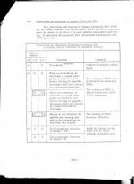
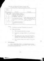
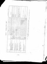
This is the SH according to the orientation board literature:

spindle maint SH p1.jpg

spindle maint SH p2.jpg

spindle maint SH p3.jpg

Here's according to the 6MB Maint manual:

6mb maint SHp1.jpg
 
Just 3 little rainbow trout. Several more strikes that I didn't hook. It's a catch and release only fly fishing stream.

I generally catch and release anyways. If I get a bagger Snook during season, will take one home occasionally.


Back
Top