Greg B
Hot Rolled
- Joined
- Jul 13, 2002
- Location
- Irvine, CA
Hi all,
Long story short, the machinist who used to make these cams no longer works at my company. Unfortunately, he was the type of guy who refused to teach anyone.
Specifics, Fadal VMC4020 with 5th axis.
Tools :
#1 c'drill
.500 roughing cutter
.500 finish cutter
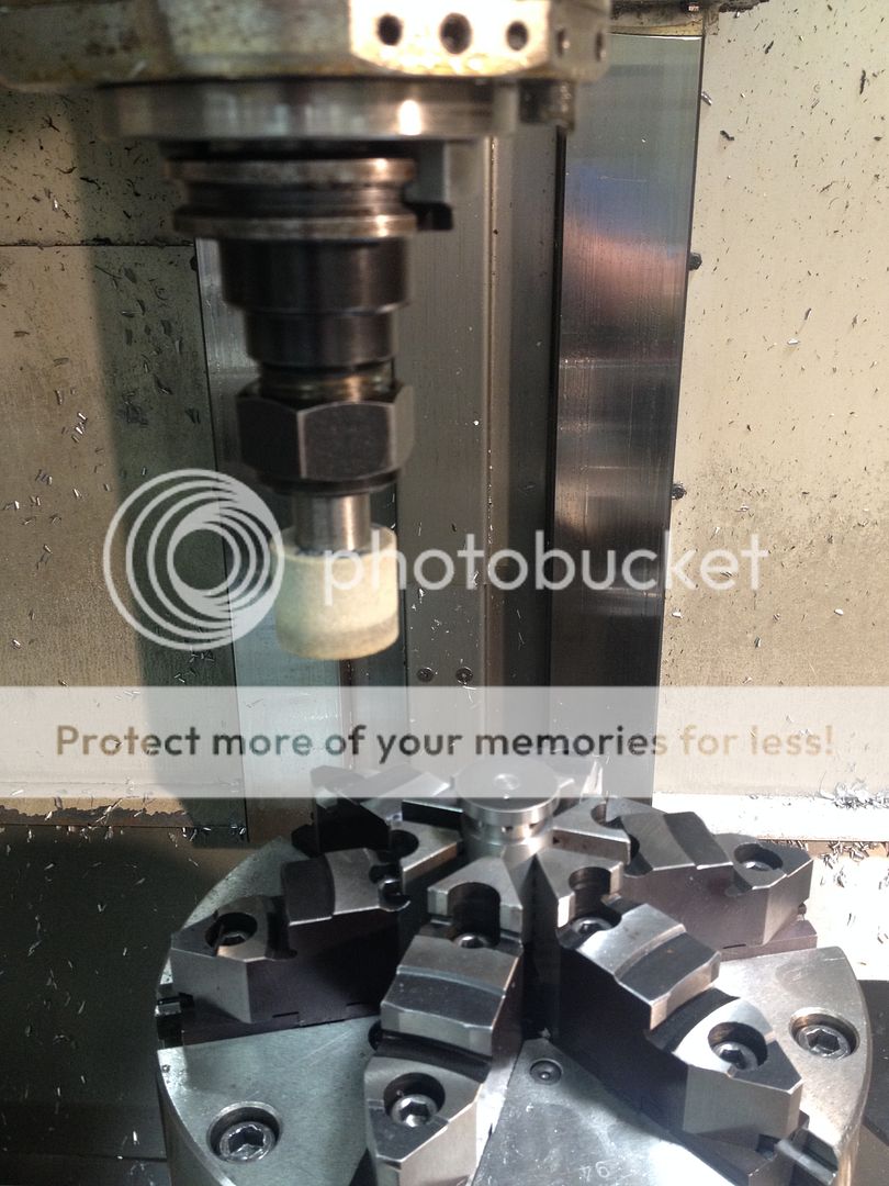
1.625 grinding wheel
The part runs with the B axis pointing straight up.
The set-up sheet tells nothing beyond rotary set up and the programmed radius for the grinding wheel.
What I cant figure out, is how to figure the data for the F & R & V.
I have never had any experience with macros, and I'm at a total loss.
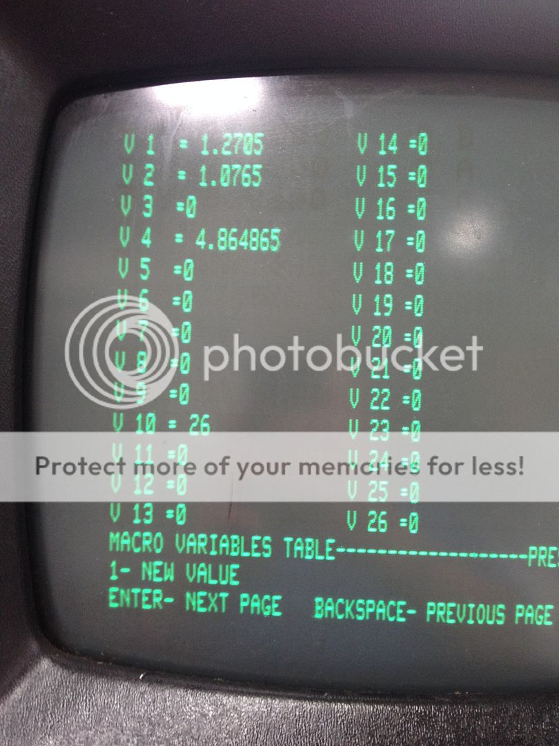
I've at least found the variable table in offsets.
I'll get some photos posted tonight, I realize its hard to visualize.
The cam is small, approx. 1" diameter.
This is what the program looks like:
O1111( CAM, +-.040 TRAVEL)
(05-12)
(ALL PART CAME OUT PERFECT AT +.003 OVER)
(DIM. 542 AT 270. DEG. SHOULD BE .545)
N1 L100
N2 G1 X0 F+R1
N3 G91 A-90. Y-0.084 F+R2
N4 A-270. Y0.084
N5 Y-0.05 F+R1
N6 X-0.5
N7 G90
N8 M17
N9 M30
N10 M0 (UPDATE 'LETTER' FOR PART #)
(ENGRAVE DATE AS MONTH-YEAR 'LETTER')
(LETTER A FOR THE 1ST PART)
(THEN B FOR 2ND AND SO ON)
N11 G0 G90 G49 Z0 H0
N12 G54 X-10. Y0
N13 M6 T1(#1 C'DRILL)
N14 Z4. H0
N15 G0 G90 G57 A135. B-270. X0.05 Y0
N16 M62
N17 M3 S2000
N18 G43 Z0.1 H1 M8 D1
N19 G1 Z-0.005 F1.
N20 X0.59
N21 G0 Z0.1
N22 X-0.25 Y-0.32 A180.
N23 L9201 R+0.05 R1+0 R2+0.1 R3+0 Z-0.005 F1.(05-06 A
N24 G0 Z0.1 M5 M9
N25 Z4. H0
N26 G54 Y0 X-10.
N27 M1
N28 M6 T8(.500 ROUGH)
N29 Z4. H0
N30 R1+3.(TABLE FEED )
N31 R2+100.(ROTAR Y FEED)
N32 G0 G90 G57 A-270. B-270. X-0.5 Y-0.72
N33 M62
N34 M3 S600
N35 G43 Z0.1 H8 M8
N36 G1 Z-0.25 F40.
N37 L101
N38 G0 Z0.1 M5 M9
N39 Z4. H0
N40 G54 X-10. Y0
N41 M1
N42 M6 T9(.500 FINISH)
N43 Z4. H0
N44 R1+3.(TABLE FEED )
N45 R2+100.(ROTAR Y FEED)
N46 G0 G90 G57 A-270. B-270. X-0.5 Y-0.72
N47 M62
N48 M3 S700
N49 G43 Z0.1 H9 M8
N50 G1 Z-0.25 F40.
(ADD .001 TO Y-.71)
N51 Y-0.711
N52 L101
N53 G0 Z0.1 M5 M9
N54 Z4. H0
N55 G54 X-10. Y0
N56 M1
N57 M6 T10(1.625 DIA. GRINDING TOOL)
(PART SHOULD FINISHED AT +.003 OVER AS REQUIRE)
N58 Z4. H0
N59 R1+2.
N60 R2+100.
N61 # V1=1.2715
(R+.458+.001 FOR 3 CUTS)
N62 G0 G90 G57 A-270. B-270. X-0.5 Y-1.5
N63 M3 S6000
N64 G43 Z1. H10 M8 D10
N65 G1 Z-0.65 F30.
N66 # V2= V1+(D10/2)
N67 # R3= V2
N68 Y- R3 F+R1
N69 L101
N70 Y-1.5
N71 X-0.5
N72 # V1= V1-.0005
(FIRST CUT)
N73 # V2= V1+(D10/2)
N74 # R3= V2
N75 Y- R3 F+R1
N76 L101
N77 Y-1.5
N78 X-0.5
N79 # V1= V1-.0002
(SECOND CUT)
N80 # V2= V1+(D10/2)
N81 # R3= V2
N82 Y- R3 F+R1
N83 L101
N84 Y-1.5
N85 X-0.5
N86 # V1= V1-.0002
(FINISH CUT)
N87 # V2= V1+(D10/2)
N88 # R3= V2
N89 Y- R3 F+R1
N90 L101
N91 Y-1.5
N92 X-0.5
N93 # V1= V1-.0001
(FINISH CUT)
N94 # V2= V1+(D10/2)
N95 # R3= V2
N96 Y- R3 F+R1
N97 L101
N98 Y-1.5
N99 X-0.5
N100 G0 G90 Z1. M5 M9
N101 Z4. H0
N102 G54 X-10. Y0
N103 A0 B0
N104 M2
%


