I would like some help/advice on a movement I would like to do if possible.
I have done a diagram so visually I hope it explains it better than text.
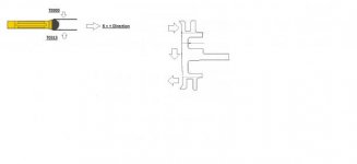
The radius insert in the picture is how it faces operator in the machine. It will be plunging in the X direction plus.
T0303 will be measured by touching front edge of insert and TOP of insert.
T0313 will be measured by touching front edge of insert and BOTTOM of insert.
At the top of the component the insert will be plunging into the diameter under the landing in a X+ direction then feeding down a Z- movement.
As it moves to the bottom of the part it leads into a lip, I would like to switch offsets to T0313 about ½ way down so I can use that side of insert.
My idea behind this is rather than adjust the program individually as all parts are different we can adjust the Z offsets + or - in the corresponding offset of T3 to help with metal on/off, depending on the repair and what is needed per component.
(excuse the drawing it is basic but I hope it explains my situation)
Thanks for any help
I have done a diagram so visually I hope it explains it better than text.
The radius insert in the picture is how it faces operator in the machine. It will be plunging in the X direction plus.
T0303 will be measured by touching front edge of insert and TOP of insert.
T0313 will be measured by touching front edge of insert and BOTTOM of insert.
At the top of the component the insert will be plunging into the diameter under the landing in a X+ direction then feeding down a Z- movement.
As it moves to the bottom of the part it leads into a lip, I would like to switch offsets to T0313 about ½ way down so I can use that side of insert.
My idea behind this is rather than adjust the program individually as all parts are different we can adjust the Z offsets + or - in the corresponding offset of T3 to help with metal on/off, depending on the repair and what is needed per component.
(excuse the drawing it is basic but I hope it explains my situation)
Thanks for any help
")