What's new
What's new

Hmc tilt table

Badbascom

Plastic
Joined
Mar 2, 2014
Location
Hondo, TX
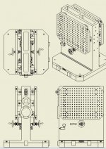
I require a method to fine adjust the a-axis alignment on my 4 axis HMC, I have come up with the attached. My question is there a better way or an off the shelf item to perform the same task? I only need a few arc minutes, not much travel. This is a big 1000mm tombstone with 1000 x 750 mm grid plates on each side. My other thought was to tilt the entire tombstone but chose this so I could have my probe calibration rings in a permanent position.


Capture2.jpgCapture1.JPG
 
Machining is going to be pretty light? Setup looks kinda cheesy to me.

If you set it once and forget it I would lean towards gauge pins in a vee and throughbolts, no hinge, no screws and no clamps.

I would expect the bitch of your design will be when you're indicating all this in with the screw adjuster and then you tighten the clamps it's going to move all over.

With solid shims (selectable diameter pins) you trail and error until you get it right and it's repeatable.

That was my 2econd thought...shim. My first was reface the sub plates.
 
These will have to be adjusted for every part. You can see but there are springs under the top clamps that always put pressure onto the differential screw. These are light weight magnesium parts I am boring, the parts are not perfect and therefore need to be corrected every time. I probe 3 points on a plane and between the B-axis and A-axis I adjust until TIR is <.0002".
 
If you're gonna do something like that:

1: put the "hinge" at the top. You don't see sine plates with the hinge in the middle. You put the pivot at one end and gage blocks at the other. You also only get half the resolution with the pivot in the middle.

2: Use conterbored holes to clamp the corners over stacks of blocks. Or over adjustable set/cap screws, if you wish it to be adjustable with screws. These should be under round pins inserted into the free corners of the plate. Just like a Sine plate.


What is the application? Do you have a slight angle you need to mill the part to while tilting? Or do you have parts that already have an angle that you need to modify, and dialing it in that way is the only way to get it flat?

Edit: i see you posted the application.
 
These will have to be adjusted for every part. You can see but there are springs under the top clamps that always put pressure onto the differential screw. These are light weight magnesium parts I am boring, the parts are not perfect and therefore need to be corrected every time. I probe 3 points on a plane and between the B-axis and A-axis I adjust until TIR is <.0002".

It looks like a really bad design for holding .002". I can't fathom .0002" with that.

You have things bending from spring pressure, stiction of smooth surfaces, deflection of all the materials and clamps. There's no way you're going to release those clamps, move the screw a miniscule amount reclamp and get what you want.

More I think about this if you only need to correct a few thou over that big span I'd make your hinge from steel flatbar with the middle relieved so it bends there. Attach your plate to one side of the flatbar and the other side of the flatbar to the tombstone.

At the bottom of the fixture I'd use a tube with one capped end captured between the tombstone and fixture plate. On the open end of the tube I would machine or buy a small bore hydraulic cylinder/piston and attach or plumb them together. Make a threaded adjuster to push on the piston. Bleed all the air out and now you have a very small movement hydraulic actuator without any lost motion.
 
Does anyone know of a tailoring table I could buy that the tombstone would sit on?

I'm reading this thread with great interest;

I have similar solutions for smaller scale components but near micron level adjustment but near ultra rigid. 5 arc second tolerance / sensitivity + small tilt range of 5 degrees / - but (frustratingly) can't "share" at the mo' / 100% help solve what you are doing.

Agree with @dandrummerman21 putting the hinge in the middle is a 'Noob"-ish / common yet very understandable mistake.

With limited information I'd say the following,

- Don't tilt the tombstone at it's base on the plane of the B axis; I think the general approach you have is right.

There are different "hinges" industrial strength flexture joints that are commercially available. (NASA uses those) might dig up.

- I like Garwood's thinned out flex bar idea - I've seen that used pretty successfully.

- In general machine tools are "Odd" as compared to other precision engineered systems as typically they don't have a "Course" - "Fine" and "Ultrafine" set of separate (nested) mechanical adjustments - especially for rotations.

_________________________________________________________________________________________


@Badbascom how many magnesium parts have to be bored on each side of the grid plate ?

More than one ?

Or how many bores (large I assume) relative to the part have to be made on each side of the tomb stone ?

- Are you looking to automate this process a bit more though probing + other adjunct techniques (I have an idea about that.).

[So as I understand, you probe three reference surfaces at three points on a magnesium (casting maybe ?) - determine the corrective angles of the plane of the part that needs to be made for the (perpendicular) bore, (pitch and yaw corrections - B axis and created "A-axis" rotation, THEN make X and Y (delta / offsets / corrections on the main spindle for boring : and depending on profile and severity of angular correction might need an offset / correction in Z ? ] - Sweep the rough bore/ hole / surface ? ].
 
Just one part on each side. The bores are anywhere from 2.5 in to 12 in. I want the universal grid to accommodate all sorts of parts that we may encounter. One thing that may not be evident is this is a giant tombstone, 1000mm x 1000mm pallet, the grid plates shown are 2" thick, 1000mm x 750mm.

We have a fixture similar to my concept and it works OK but takes an excessive amount of time to dial in, it uses barrel hinge at bottom a cam type adjuster at top with pull springs to hold the plate against the cams. Also it uses flexural steel hydraulic brakes that hug the tombstone sides from both sides at the top whereas my brakes are on the same side and the hinge allows lateral movement meaning as hydraulic pressure is released the fixture would slide to the right and then under when clamping, slide to the left until the braking blocks mated. The reason I put the hinge in the middle is so I could use die springs at the top to always put pressure on the differential screw, although in practice the weight alone would probably be sufficient.

In process my probe program would measure the appropriate plane and then direct the operator to turn the differential screw so many turns, in this design one rotation equals 2 thousandths, I might put a waterproof indicator on there to make things easier.

I am taking the feedback and now working on what you specifically not recommending, tilting the tombstone. My current concept use a living hinge, a wedge block for height adjustment, a plurality of hydraulic work supports under the tombstone and then 4 big hollow cylinders at each corner. Still playing around with this idea.Capture3.JPG
 
Just one part on each side. The bores are anywhere from 2.5 in to 12 in. I want the universal grid to accommodate all sorts of parts that we may encounter. One thing that may not be evident is this is a giant tombstone, 1000mm x 1000mm pallet, the grid plates shown are 2" thick, 1000mm x 750mm.

We have a fixture similar to my concept and it works OK but takes an excessive amount of time to dial in, it uses barrel hinge at bottom a cam type adjuster at top with pull springs to hold the plate against the cams. Also it uses flexural steel hydraulic brakes that hug the tombstone sides from both sides at the top whereas my brakes are on the same side and the hinge allows lateral movement meaning as hydraulic pressure is released the fixture would slide to the right and then under when clamping, slide to the left until the braking blocks mated. The reason I put the hinge in the middle is so I could use die springs at the top to always put pressure on the differential screw, although in practice the weight alone would probably be sufficient.

In process my probe program would measure the appropriate plane and then direct the operator to turn the differential screw so many turns, in this design one rotation equals 2 thousandths, I might put a waterproof indicator on there to make things easier.

I am taking the feedback and now working on what you specifically not recommending, tilting the tombstone. My current concept use a living hinge, a wedge block for height adjustment, a plurality of hydraulic work supports under the tombstone and then 4 big hollow cylinders at each corner. Still playing around with this idea.View attachment 319489

Just a quick one - will come back later.

Yup Differential screws can be incredibly accurate and precise...

Yup - Wedge blocks super useful and can bring an extra level of well supported precision.

I kinda get the process you've been through and need for a more generalized / expandable / more flexible capability + where further adjustments mechanically may come from.


^^^ General idea / take away is that after probing (in more general terms) the spindle can have a tool (assuming slow controlled rpms) to undooo locking bolts, then adjust positional screw mechanisms, then lock again, probe to check then use computed offsets and "Cut" / Bore.

I understand the video is doing a different process but "In spirit/ theme" spindle can turn screws and "Handles" and locking screws / clamps.

~ Traditionally the longest "beam" length is used for angular adjustment to get greater precision and accuracy and springs for some kinematic tables (large and small) can be put close to the adjustment mechanism (usually in tension - rather than compression -per se ). You know how you want to do things so I'm not changing your "Style" and wants in design engineering.

_____________________________________________________________________________

I understand the sizes and weights you are dealing with,

Did kinda make me wonder about machines like the HAAS UMC 1000 for this kind of work / work piece size + automated probing routines and corrective more intelligent automated routines, 8 arc mins should be well within the capability of even a HAAS large 5 axis machine (on it's rotary axes). (no tombstone required and they have a giant palette system ? ).

Just a rando thought.

Safer for the operator ? >>>> Magnesium / Magnesium alloy ? [Not sure how you are handling all that .]. presumably having the operator not climb into the machine is a "smidge" safer / less incendiary ? (maybe ?).
 
Wow I had never ever thought about the using the machine to make the adjustments, a little too advanced considering the time constraints I am under but this is wonderful insight to have going forward. Thanks


Back
Top