What's new
What's new

How do large lathe's and mill-turns handle C axis movement?

Jaxian

Stainless
Joined
Feb 24, 2013
Location
Santa Cruz
I was watching Edge Precision on YouTube a while ago and a question jumped to mind and I realized I had no idea what the answer was and figured I would ask.

He uses a big Mazak 5 axis mill-turn, like a Integrex 650 or something. So my question was while watching it execute a bunch of C axis moves was:

Do these large mill-turn machines use the main spindle motor for the very accurate C axis moves? If not is there a positional motor? How does it integrate in the power flow?

I mean just looking at the motor setup in my SKT250 it has a 30hp motor connected through about 4' of ribbed Kevlar belt and a transmission before getting to the actual chuck. Doesn't seem like a very good setup for accurate C axis positioning.

Thanks for any insight guys. Was just a thing it had never dawned on me I didn't know.
 
My idea of a big machine with C axis is something like those You Ji VTL's I ran. An any case I don't see how the engineers think accurate positioning with a few V-belts to a 10-20K pound chuck is going to work. Positioning, OK maybe, but continuous I have never had any luck (See my old post about getting pinned up against another machine for trying to rigid tap 4" pipe with a 4:1 torque multiplier with 50hp spindle:nono:).

Smaller machines like my old Kia SKT-21LMS actually held great tolerances through the belts. They were a maintenance nightmare so I had them apart many times and never saw anything looking like an encoder on the spindle so my guess is it was just the drive encoder positioning C.

You raise a good question about the higher end machines and positioning. Now you have me wondering if they are using encoders on the spindle rather than the motor on machines like Okuma, Mori, Mazak,,,, I don't ever recall seeing a positional motor on a C axis before.
 
He talked about it in a video last year. Just dig around on his channel some more
 
Do these large mill-turn machines use the main spindle motor for the very accurate C axis moves? If not is there a positional motor? How does it integrate in the power flow?

Yes. The Mazak Integrex has in integral spindle motor that also does the C-axis positioning moves. Our Integrex i-400s has that type of spindle motor.

Older Mazaks from the 80's had a separate C-axis servo that was coupled (and uncoupled when not in use) to the spindle to execute C-axis movement. My 1986 Mazak QT10N ATC/MC is an example of that style.

EDIT: It appears like the really big Integrexes have a separate servo as well. Snip from Mazak's website:

The INTEGREX e-670H-S main and second spindles are high-output integral spindle motor types with two gear ranges for a wide scope of heavy-duty machining applications. A drop-worm system that delivers the same positioning accuracy as a machining center rotary table drives the machine's C-axis (0.0001-degree increments).
 
It's hard to see from the video above because the 2d drawings have so many components, but the main spindle on his older integrex has a concentric worm gear permanently mounted on the spindle shaft just like a rotary table. The difference is that the linear worm mechanism that drives it has a pivot bearing on one side, and a short pneumatic cylinder complete with an adjustable hard stop on the other side of the main spindle shaft.

So when the cylinder pushes, the linear worm gets pressed against the main spindle concentric worm gear and engages with the teeth; at this point the main spindle is in indexing mode and cannot be back-driven by cutting forces. The adjustable hard-stop on the piston end of the mechanism is what allows you to take the backlash out as the machine wears from long term use.

Compared to a direct drive / integral only type of machine, the worm gear lets you take super heavy cuts while the axis is in motion. Both types are compatible with brakes and ring encoders, not sure if the integrex has those or not.
 
I was watching Edge Precision on YouTube a while ago and a question jumped to mind and I realized I had no idea what the answer was and figured I would ask.

He uses a big Mazak 5 axis mill-turn, like a Integrex 650 or something. So my question was while watching it execute a bunch of C axis moves was:

Do these large mill-turn machines use the main spindle motor for the very accurate C axis moves? If not is there a positional motor? How does it integrate in the power flow?

I mean just looking at the motor setup in my SKT250 it has a 30hp motor connected through about 4' of ribbed Kevlar belt and a transmission before getting to the actual chuck. Doesn't seem like a very good setup for accurate C axis positioning.

Thanks for any insight guys. Was just a thing it had never dawned on me I didn't know.

Depends on the machine tool builder and technology at the time. Today, the C axis is usually equipped with an absolute rotary encoder, and a braking system as well. When making large or heavy cuts in C, you would engage the high pressure clamp function, then disengage when rapid or homing.
 
My SQT 250 MS has integral spindle motor and a disc brake too. My newer QT250 MSY has a larger motor, disc brake too. It also has C axis on the sub spindle but do not know if the sub has a disc brake. I would guess it does.
 
Great information guys. I love machinery so looking into how companies implemented this C axis functionality is very interesting to me. Also found out by bringing it up with non machinists who have come through my shop that it is of no interest to normal people. Their loss. :D

So the consensus is that smaller machines or ones with servos as their main drive can use that directly to perform C axis moves. Larger machines would use some type of secondary servo that is engaged when C axis positioning or movement is required. Sort of like when you engage or disengage the worm on a rotary table by moving a lever.

So the detail of how brakes are used to resist cutting forces is interesting, I am going to go see if I can find some drawings of how this stuff is implemented.

Another detail that jumps to mind is positional accuracy. I know on like my basic VMC (a Doosan) if I wanted to do high accuracy moves they recommended to buy scales ($5k ea :eek:) for the best repeatable results. This seems pretty common. I recall the Haas UMC discussion were people were talking about having there be scales or not on their rotary axis because they weren't consistent enough using just encoders.

So on the C axis movement I would assume they would want to put a scale on the main spindle and not the try to just use the encoder on the C axis servo because it would lose it's place every time it was engaged or disengaged. Do you think they just try to use a standard encoder attached to main spindle motor or do they put some kind of scale there to get the required accuracy? Is there such thing as a circular scale?

Thanks for the information guys.
 
I wouldn't say there is a consensus necessarily, but in general, there is no way to avoid the direct linear relationship between torque and amperage in direct-drive / built-in motors on machine tool rotary axes. This means if you take a heavy, off-center cut in any CNC machine with a directly driven rotary axis, you will need to run a lot of electric current to the motor to keep it from back driving. Having a disc brake, curvic coupling, or shot pin mechanism allows the machine to take heavy cuts when stationary. Rotating the axis with the brake engaged is only possible on machines that have a ton of torque; it is unusual for the motor on an axis to be able to overpower the brake on that axis, but it would still waste the majority of the electric power going to the motor and generate a lot of heat in the control electronics and in the servo.

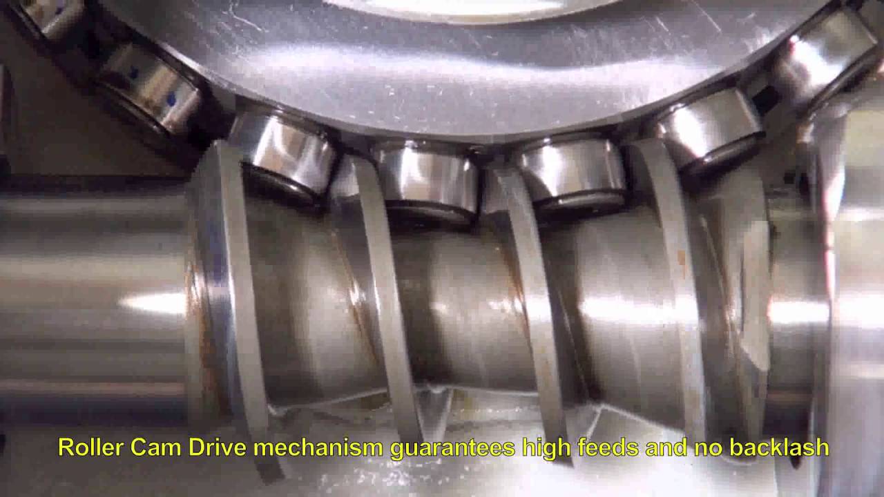
Worm gear mechanisms are generally non-backdriveable, but can still move accurately while under heavy torque loads. There is also a mechanism nearly identical to worm gears called roller-cam drives that have the same form factor, but have no backlash and have a lower mechanical gear-down ratio with greater mechanical efficiency. They can be backdriven by cutting forces but are superior to worm gear drives in most ways, except for cost. I don't think it would be possible to have the same type of pivot mechanism that can engage a worm gear work on a roller-cam system, as the rollers and worm must be assembled super accurately and might not be able to "swing" into position. So a roller-cam drive would have to engage the machine spindle by axial movement rather than swinging in radially.

maxresdefault.jpg


I was recently looking at a quote on a 400mm 5 axis machine; getting glass scales on all 3 linear axes would cost about $7,550 more than base price (~2,500 per scale) and rotary axes would cost between $3,600 and $4,400. They include a 10 arc-second rotary scale on the A axis (trunnion) with the base machine price. To upgrade it to a 5 arc-second scale costs between $230 (Siemens) and $1,150 (Fanuc), with Heidenhain in the middle. They didn't say in the quote who makes the linear and rotary scales, but I've heard that Heidenhain makes all the scales and most machine tool builders just use slightly different cables or whatever to make them work with Fanuc and Siemens controls. The base price of this machine is 89k for the Fanuc version and 92k for the Siemens version, I toured their whole factory and I believe the machine is mechanically (almost) identical to a Doosan DNM 4500, except this builder puts 3 sets of linear roller bearings on the X axis. Very rigid looking machine, it's a shame we can't see these types of prices in the US.

BTW, all of the machines with controlled rotary axes rate their accuracy in arc-seconds. All of the quotes I've gotten tell me the same thing; that worm-gear, roller-cam, and direct-drive rotary axes are all precise to within 20 arc-seconds when brand new and are mainly limited by the encoder fitted to them. Worm gear rotaries have backlash within the 20 arc-second range and this number increases over time as they wear from use. Direct and roller-cam systems have no backlash and don't wear out. If you crash a roller-cam rotary, it will backdrive rather than break or damage the rollers, but you can still damage the main axis bearings if it's a hard crash.

20 arc-seconds corresponds to a rotational inaccuracy of 0.00048" (12 microns) on the surface of a 6 inch (160mm) part. So if you get a machine like the one quoted above with 5 arc-second rotary scales, your best rotary positioning accuracy will be right around 0.0001" on a 6 inch part. With linear scales and an air conditioned shop, that 0.0001" accuracy is not bad for a $100,000 5 axis machine.


Back
Top