What's new
What's new

how to locate a phisical x address on fanuc 0md, probe install

lowCountryCamo

Stainless
Joined
Jan 1, 2012
Location
Savannah, Georgia, USA
I bought a used marposs spindle probe system. I am preparing to install. X8.7 is the skip signal address, so says my manuals. Where "physically" is this located? I have searched and cannot find this information.

Thank you,
Steve A
 
Most builders would bring that from the I/O board connector out to a terminal strip. It's also common for the terminal to be labeled something other than X8.7. In the case of the skip signal something like SKP or the like.

Post a picture of the wiring diagram page where you found X8.7. Somebody can probably help more with that in front of them.
 
So the schematic is showing that the skip signal is coming off the I/O board on connector M18 pin 49 and it appears to be labeled 500 and stop at a terminal T0. The notation LK1(B1,B2) may be significant here as well. LK1 may be a designation for a terminal strip B1 or B2 may be +24VDC and whicever one is not is the input. You'll have to poking around the cabinet looking for terminal strips and see if you find wire 500 or a strip labeled LK1. If you don't find anything that way, you can always find connector M18 off the I/O board and trace the wire on pin 49.

As with all this type work be super careful with the wires you choose to connect to. Years ago I had to replace the entire control on a Yang lathe. The owner bought a used barfeeder for it and opted to install it himself. He mistakenly wired up the end of bar input signal to 220V instead of 24V. All was fine and I suspect he patted himself on the back for a job well done until he ran out of stock. The 220V fed into the 24V side of the control and damaged every single board in the control and out to the display panel. The better part of $20k down the drain.
 
I've cast an eye over that. I'm no different to VanC. I concur.

We get the same wire / pin numbers,

Regard Phil

(Adding on Edit) I've also seen 415VAC shoved up to a 24VDC arse. It happens, bar feed to CNC interface.
 
The 220V fed into the 24V side of the control and damaged every single board in the control and out to the display panel. The better part of $20k down the drain.

I was working on a machine with a Dynapath Delta 20 control. It died, the power supply failed. The customer bought a new power supply and chose to install it themselves. They hooked up 110VAC to the output side. Anything that ran on 24VDC got a short burst of 110VAC until the fuse popped and the filter capacitors in the power supply exploded.

Long story short, they bought anther machine...
 
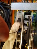
Every Time I come here for help you guys nail it from the start. Found m18 Honda coming out the I/O card with a small black wire hanging separate from the ribbon. Tracked that back to terminal 500. :bowdown:
m18 ribbon.jpg500.jpg
 
dia.jpg
probe diagram2.jpg
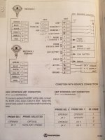
I have already learned much from this project. I do have a couple more questions. I feel I am way off base but, looking at the diagram, is this how I would connect the interface box to the cnc. I may not need 2 and 3 now as I only have the spindle probe. Someone installing this earlier scribbled on the diagram. I think he marked the terminals he used. I read the manual before asking but could not find my answers. I had trouble getting the picks straight. Thank you very much.

1 - 0vDC
2 - 24vdc
3 - 24vdc
5 - an mcode if used
6 - ?
7 - 24vdc
8 - terminal 500 skip
9 - 24vcd
10 - ?
11 - 24vdc
12 - ?
13 - 24vdc
14 - 0vdc
15 - ground
 

Attachments

  • probe diagram.jpg
    probe diagram.jpg
    92.7 KB · Views: 428
  • dia.jpg
    dia.jpg
    92.7 KB · Views: 282
  • dia.jpg
    dia.jpg
    92.1 KB · Views: 270
Never installed a Marposs so......

This is my take..

1 0Vdc
2 n/c
3 n/c
4 n/c unless you have an M-code output for activating probe. If you do I'll need more info.
5 n/c unless you have an input for "probe ready"? I'm guessing a bit here without Marposs info.
6 n/c same as above.
7 +24Vdc from CNC! This is important. This needs to come from the Fanuc power supply, not an auxiliary power supply.
8 Terminal 500
9 n/c unless you have an input for "low battery"?
10 n/c same as above.
11 n/c unless you have an input for "probe error"?
12 n/c same as above.
13 +24Vdc from CNC or other power supply.
14 0Vdc from same supply as above.
15 Machine ground.
 
Last edited:
24v.jpg
contact.jpg
keep relay.jpg
So I located a 24v and 0v terminal on the board in panel. Is there a good way to know if that is cnc 24v and not from the mtb power supply? Concerning the use of an mcode to turn the probe on, I found a m68/m69 that operates the conveyer contact. I don't have a conveyer for this machine and would be willing to use that if possible. That mcode also activates a keep relay in the last pic. In this case, would I need to locate the signal that closes that contactor, or something else?

Thanks
steve
 
Per the schematic page you posted earlier DC24VA is a Fanuc 24V. I'm going to guess that there may be a corresponding DC0VA or maybe 0VA. There may be others from the Fanuc supply but without the rest of the schematic I can't be sure.

The M68/M69 to turn the probe on and off seems like it has potential. They are probably not requiring an MFIN (M Finished) signal to verify completion. That saves quite a bit of dinging around to provide MFIN. M68 turns on the "ice cube" relay (clear housing ones that you called keep relay). The contacts of that relay switch on the power to the coil of the 3PH contactor for the conveyor. To use that for the probe you first need to figure out what voltage the coil of the contactor uses. If it is 24V then you could just take that wire off the coil of the contactor and connect it to terminal 4 of the probe interface. If the contactor coil is 100V or 200V then you have some additional figuring out and wiring to do.

Sorry to be so vague about all this. Without having the entire schematic and a copy of the ladder I'm shooting a bit in the dark.
 
I am close to completing this project but still lack a m68/m69 dc24v to turn on and off the probe. M68/M69 turns on and off an ice cube. This relay activates the ac110v coil on conveyor contactor.
conveyor contactor 110v.jpg
It seems my choices are:
1. to use the y52.6 M2 connector pin 12. Is this a constant 24v when m68 is called or just a pulse? Would this even work?
2. Pull the 3phase wires from the contactor and run my own dc24v through this contactor to the probe. Any comments or potential problems here. This would be huge overkill for just dc24v. But would it work?

The probe manuals provided a single paragraph of each language on each page I copied, cut, and pasted (literally), and recopied to get the interface wiring details on one page. This is it
marposs details.jpg
Couple other questions:
Does the Fanuc I/O look for, and give DC24v? Is it constant, or pulse?
I also found a page in my electrical manual titled add m code, ever seen this?
add mcode.jpg
 
I am close to completing this project but still lack a m68/m69 dc24v to turn on and off the probe. M68/M69 turns on and off an ice cube. This relay activates the ac110v coil on conveyor contactor.
It seems my choices are:
1. to use the y52.6 M2 connector pin 12. Is this a constant 24v when m68 is called or just a pulse? Would this even work?
2. Pull the 3phase wires from the contactor and run my own dc24v through this contactor to the probe. Any comments or potential problems here. This would be huge overkill for just dc24v. But would it work?

1. This would probably work. The behavior of output Y52.6 is determined by how the machine builder wrote the ladder. Usually the outputs for items like a chip conveyor are held on until the M code to turn the device off is executed. Based on what I've seen in the schematic pages you have posted this looks to be the case and makes it an attractive way to turn on your probe.

2. This would also work. As you said using the contactor is massive overkill, but it would function. This also an easy and attractive way to turn on the probe.


Couple other questions:
Does the Fanuc I/O look for, and give DC24v? Is it constant, or pulse?

The Fanuc control can source the 24VDC on outputs or it can sink the 24VDC on outputs. It is the machine builders choice. The schematic pages you posted show that sourcing 24VDC on the outputs has been used by this builder. This is the most common method used with Fanuc controls by Asian builders and IMO the best/safest. Sinking outputs have the risk of an insulation failure causing a device to operate when not commanded. Whether an output is a pulse or held is determined by the machine builders ladder program.

I also found a page in my electrical manual titled add m code, ever seen this?

Additional M-codes like you have shown in the schematic page are intended to be used with a device that can provide a completion signal. The output typically is maintained though can be a pulse as determined by the builders ladder program. Program execution is halted until the corresponding M-Finish signal input is activated. An indexer device is a common usage of this type M-code. The CNC executes the M-code and the CNC then halts further execution of its program. The indexer control then performs its operation and on completion outputs a signal to the M-Fin input of the CNC. When the the ladder program in the CNC reads the state change of the M-Fin signal it resumes execution of its program.

Using that type M-code to turn on a device that does not provide an M-Fin signal requires wiring in a timer relay to provide a "fake" M-Fin signal and a latching relay to hold the output. Accordingly, another M-code would need to be wired to unlatch the relay to turn the device off and another timer relay wired in to provide the M-Fin for that M-code. Total PITA.
 
Hoping not to be overly tiresome, I have found one more question regarding DC24v_ labeling. In MTB schematics, real world, and Fanuc Connection, I see 4 different DC24 labels and one 0v.

DC24VA "joined" to X inputs on schematic (including skip signal)
DC24VC joined to Y outputs on schematic, and "seems" to originate from main transformer/REC1, (a MTB power supply) see attached pic
DC0VC
DC+24E Found only in Fanuc connection manual. My +24E is not connected in the front of my Fanuc power supply.

I wired the start and probe to DC24VA; main interface 24v and 0v to the MTB supply-REC1.
Grounded to closest system ground brass plate.
-Is this naming convention common?
-Are these different circuits with different functions?
transformer and REC1.jpg
 
Each machine builder chooses their own labeling conventions and wiring architecture, though some builders copy what others have done. Figuring out those conventions from one builder to the next is one of the joys:rolleyes5: of doing field service on a variety of makes. After you have gotten a half dozen or so figured out though they all start to make some kind of sense (until one starts looking through a Euro built machine schematic).

The DC+24E from the Fanuc power supply can power a small amount of power to External devices. It is occasionally used on smallish simple machines with few outputs.

You have connected the probe system how I would have based on the info you have posted.

The machine builder DC24VC is used to turn power solenoids and relays and contactors. Those type devices are very insensitive to poor power. The Fanuc output board uses Solid State Relays (SSRs) to switch power to those devices. The machine builder can save money by providing their own simple power supply.

Inputs to the CNC are almost always powered from the Fanuc power supply. Using a simple power supply to power inputs is risky due to potential voltage fluctuations, ripple, and noise. The Fanuc power supply is a pretty sophisticated switching supply with really nice electrical characteristics.
 
Lack of "free" M-function to switch the probe on and off is quite frequently the biggest problem when retrofitting the system to existing machine. In your case you have M68/69 available, but in normal mode of use the probe could be activated each time the chip conveyor is switched on and off. In order to overcome such problem I use small, simple and cheap PLC which is programmed in such way that it outputs the PROBE ON signal only after receiving 2 0.5 second duration pulses during the period of 3 seconds. Small program like this one
M68
G4X.5
M69
G4X.5
M68
G4X.5
M69
assigned to new M-function causes the PLC to generate the PROBE ON. Next M68 M69 pulse switches it OFF.

By the way, which type of Marposs do you have.
 
Lack of "free" M-function to switch the probe on and off is quite frequently the biggest problem when retrofitting the system to existing machine. In your case you have M68/69 available, but in normal mode of use the probe could be activated each time the chip conveyor is switched on and off. In order to overcome such problem I use small, simple and cheap PLC

This is very true for many probe installs.

This little PLC is my choice when faced with a need to add some logic to a machine when processing additional M-codes.

SG2-12CR-D

I've used them for installing probes, but also parts catcher/conveyor setups. Low cost and easy to program with free programming software.


Back
Top