What's new
What's new

Hyundai Kia SKT 200 Turret alignment

valterroque

Aluminum
Joined
Nov 13, 2017
Hi everyone
I am starting this thread to detail the process of alignment /correction on my 2006 Hyundai Kia SKT200.
No native English here so apologies for any typo.
Also no previous lathe experience, but not new to CNC.

I got this machine used and in need of good maintenance check.
After some initial problems that i manage to solve either by myself or with the help of forum members i come to the
point of checking its accuracy.
After trying to educate myself on the subject reading here in the forum or in Youtube videos (thanks WES) i believe that i might be able to
correct its problems myself. However this feels intimidating and i will certainly need the help/suggestions from the forum members here.

So i start by manually machine a little piece of alu bar i had around.
Initial impressions of the dimension looks good overall. Will need to try with a longer bar to check for a noticeable taper. on 40 mm no taper.
However it is leaving a tit in the middle when facing.
So today a start to document the procedure and looking for advice.
I post some photos that show the turret and what i already did .
photo1 / Machine:
kia.jpg

Photo2 - I placed a indicator on one of the tool slots and move it on X. The difference on this small run was about +/- 0.06 mm.
turret1.jpg
Photo3 - I placed a indicator on one of the toll pockets guides and run it on Z. No apparent move or 0.01mm.
maybe should check on a longer surface.
turret2.jpg


Photo4 is from the inside off the little front cover. I do see 4 bolts in there but i have my doubt on what to do here. I was hoping to find some empty space for the pins but either this pops up after removing this bolts or they can only be accessed by removing the turret.
My guess is this pins are already gone considering this machine is from 2006.
Looking for advice.
insidefrontcover.jpg

Thank you
Regards
 
I will try to type things up and add annotated photos later, but I'm slammed with work right now. Here's a video with me rambling about how I did mine though:
YouTube

Basically, the center cap is not what you're after. The outer bolt circle is what you need to loosen. On mine there are two bolt patterns, one with a larger setscrew in it and one with a smaller setscrew. Remove all of these setscrews. One set of them is covering holes for dowel pins (If you're way out of alignment, you can use these to get it close. Do not leave the pins in), the other is covering socket head cap screws. The socket head cap screws are the ones that actually lock the turret alignment. Loosen these (don't remove) and you should be able to adjust the turret. Sweep your turning holder pocket in X and adjust until you get no movement. Also check a drill holder and make sure it's also on centerline. Your X value may be out a little, but you're not worried about that right now.

Once you have it aligned to your satisfaction, tighten it all up and reassemble. You can adjust your X0 position (which may have moved a little) with the gridshift param 1850. Sweep a drill/boring holder, note the difference in X from zero, and if you're in diameter mode then halve that number. Convert to metric (if you're not already using metric), and add or subtract from the grid shift X value. If you've done this right, indicate again and check that X0 is correct. If your machine won't zero return and gives a software overtravel alarm, start up while holding P+cancel to ignore the software limits and allow it to find the hardware switches. Reboot after this and you should be all set. Test carefully, and remember you will need to reset all of your tool and work offsets.

Do all of this cautiously as your machine may differ from mine, and I may be missing a step or misremembering. And of course note the original values for everything before changing parameters.
 
Thank You

I will try to type things up and add annotated photos later, but I'm slammed with work right now. Here's a video with me rambling about how I did mine though:
YouTube

My friend, your video is priceless for me. You just answer a ton of questions.
I am deeply grateful that you take some time for helping me.
I will follow your procedure next week and update or post questions as it goes.
Thank you.
Regards
 
Update1

I am surely the most unlucky person.

Found some spare time and went to try your suggestions.
Power the machine on, grab a dial indicator and sweep the tool holder in X to confirm how much is the deviation. (0.06mm)
So i decide to index to other tool pocket/holder to check if the difference was similar, and the turret somehow blocked when indexing.
It pop up some alarm power clamp error or Turret index time over as i can recall and now is outputting
NO. 2061 AL-61 turret setup error.
Now i have a dual problem.
First i have never done a turret reference procedure manually or whatever it is called.
Second this damn machine does not look it has the little marks to align on it like some do. Fortunately i had marked a line with a pen marker before but it is on T8.
This is curious because i have also seen a new Doosan lynx and it does not have those marks on it also.
The place where it is, its a teaching institution and they have no clue what to do if the turret loses its reference.
Their solution is to call tech service.
Need to investigate now how to reference this turret.
Regards
 
Also the led on the control with the turret sign is on.
I can move axis manually but cannot reference turret.
 
Like I said in your other post "Those nit picky bastard machines". For such a great little machine they will give you a lot of grief.
I think this link to referencing Kia has been listed once but its the best one I have seen. Also, take the two Philips head screws out and the alignment marks should be under there.

YouTube

Also while you're dickin around back there check to see if coolant spews out the back of the turret. If so there is a set screw behind the active tool station. remove it but keep pressure on it as that spring will magically disappear if it gets past you. Take a right angle scribe Fixed Two Point Scriber | General Tools & Instruments to hook the bushing and pull it out. I made about 6 at a time out of UHMW as they go out with the slightest chip getting behind the turret.

Thanks G-coder05.
I remember you mention that about the turret problem. That is why i marked with a pen a line crossing the movable part and the fixed part "Just in case".
However it was in Tool08.
I will follow that procedure and updated as it goes.
Machine is not loaded with coolant yet. The good thing its there is no waiting jobs for it. But i would eventually like to make this machine run.

Many thanks
 
Hi
Is your SKT200 like mine?
I am having difficulties in finding the PMC maintenance page on my Fanuc oi.
I can easily change the parameter write enable, then into System, there is 3 softkeys (pmclad,pmcdiag,pmcprm)
When i click in pmcprm, other soft keys show up ( timer, counter, keeprl... )
Click keeprl and there is a K05 00000000 without spaces in there, but does not look like the one in the video.
I can cursor on the 0000s but cannot change.
Probably i am missing something....
keeprelay.JPG
 
This quick vid shows the procedure, However for some reason I think on Kia the E-stop must be pressed also.
YouTube

Thanks, that part its not a problem.
I can enable parameter write.
problem is that i have the felling that i might not be on the correct keep relay window.
The picture above(previous post) shows the window for keep relay, however does not look like the window that is showed at the other video.
I will try to find it.
Regards
 
All of the SKT 21's iv'e seen have the markings only on tool1 and where I have put the ring in pic. It is just a line on that station and on the turret. So you need to call T1, Then do the whole turrent unclamp sequence, Hit emergency stop, index turret by hand to roughly where the line is, Release emergency stop, power up and clamp turret.

Then you need to power the whole machine down and index to another tool to make sure that it has worked. Or else repeat it.
 

Attachments

  • Turret2_LI.jpg
    Turret2_LI.jpg
    87.2 KB · Views: 223
Then you need to power the whole machine down and index to another tool to make sure that it has worked. Or else repeat it.

Hi
Thanks. I manage to do it this afternoon. Yes i find that almost non visible line. I did remove the collar but once i notice it was not there, i look down.
You can miss it if not really close.

I manage to go through the unclap procedure it was difficult to move the turret. I had to use a bar and move it slowly. I believe it was sitting on top of the curvic coupling or something else because it was very tight.
I have not try to power down and on the machine again.
But with the machine on it does not index the correct tool. But i did similar to your suggestion the same procedure with the machine on, Call T1 (machine moves to T6)unclamp procedure, rotate manually (this time was easy) to T1 finished the procedure and call a random toll but still not correct.
I guess there is more to it.
The manual have in english is limited and the full manual is in German, but the procedure is there. There is some indication to PMM parameters ...
Need to find a english version.
I will post a video about the procedure asap.
Many thanks
 
This quick vid shows the procedure, However for some reason I think on Kia the E-stop must be pressed also.
YouTube

Hi, I did the whole procedure without the E-Stop.
I think this model its not necessary. Me thinks lol.
However its indexing the wrong tools.
I think there is PMM parameter to check after resetting the turret.
 
Nope, You need to do it with emergency stop in. AND YOU HAVE TO POWER IT ALL DOWN. Even on the main switch at the back after you have done it.
What I suspect you are seeing is that the machine thinks it is at T1.
Do the whole procedure as I explained, the english version does not help much in the manual... I had to figure it out myself, and report back.

And on edit I think the reason why it did not move easily on the first try is because you did not have the emergency stop in, once unclamped and the emergency stop in in should move freely. Unless there is a mechanical fault which from your explanation is probably not the case.
 
And yes, it is a really faint line. On my SKT21 it is off by quite a bit and I actually have to get my head into the machine under the turret to see it. Don't be worried if it does not line up exactly, I suspect that is is just more of a guideline. As long as the turret clamps after you release emergency stop and clamp it.

If it throws an alarm immediatly after the reclamp don't worry. Power down the whole machine and check it.
 
If you had to use a cheater bar to spin the turret you may want to repeat the whole thing again. It should make a "Thud" when it pops loose and spin so freely that the heaviest tool spins to the bottom.
 
If you had to use a cheater bar to spin the turret you may want to repeat the whole thing again. It should make a "Thud" when it pops loose and spin so freely that the heaviest tool spins to the bottom.

Hi
That certainly was not the case. It did make the "Thud" but it was very hard to move initially. I did a second attempted and it was easier.
however did not seem so freely as you describe.
I will give it another try as per NAST555 Suggestion.
Will report back tomorrow.
Thank you all for the help.
Cheers
 
Hi
Its done. :willy_nilly:
NAST555 Suggestion was the way.
I had to do it twice I think it must clamp and then emergency stop, power all down.
At least its calling the right tools now.
Thanks guys:cheers:
 
Taper pins?

Moving on to the original intention.
So i manage to remove all the bolts covers and need to align this turret.

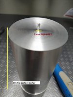
1- The machine is given me a 2mm tit on center face (X). (this is not acceptable)
2 - The machining of a round piece of stock is perfect on Z so far no taper.
rod.jpg

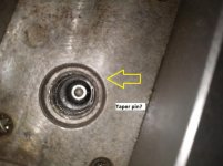
I took some photos of a supposedly taper pins inside. Can anyone confirm this?
taperpin.jpg

There are 4 holes but only 3 have this inside. One is missing and it drain a stinky black oil once i removed the screw cover.
There is a small M6 thread on them. Is it possible to remove them from the front?
As anyone removed them?
I do not want to screw up nothing more than it is.
Looking for advice here.
Regards


Back
Top