What's new
What's new

I/O Board M Code Help

Nerdlinger

Stainless
Joined
Aug 10, 2013
Location
Chicago, IL
We got a used 2000 Brother TC-S2A. If I am looking at the I/O's correctly it looks like connections 51-60 are inputs and 101-110 are outputs (24V?) I assume those outputs are turned on and off via M codes? Does anyone know which M codes turn on which outputs? And then which M-Codes do I use to turn them off? Thank you!

IO Board.jpg
 
The S2A has map-able inputs and outputs similar to the new Speedios. You are correct, the 51-60 terminals and 101-110 are your access. There are 8 inputs and 8 outputs available. 50 and 51 are the common and 101 and 102 are the common as I recall. The outputs provide a 24V output and the inputs need a circuit made (relay contacts, etc.). To map them, go into the Data Bank display, go into User Parameters, then you can access the External Input signal and External Output screens. One way to use an M code is to map an output to say M402 which is one of the choices you can map to. Choices are at the bottom of the External Output screen. Look for M402 in the choices, highlight the terminal (103 to 110) you want to map, and type in the # of the choice (16 for M402) M402 will then turn on the 24V output and M403 cancels it. Details of choices are in the operation manual and Installation manual has hook up info. Please contact Yamazen technical support 800-882-8558 for more information.
 
And if you need an M-code that waits on an input to clear (holds up NC execution until the input is received such as a clamp signal), M460 and M462 are available for that. (at least in the B & C controls)
 
What you working on? :)

I'm just looking to hook up a solenoid to use for an air blast. There are three parts we make a lot of and in an attempt to eliminate setup time I can load all the tools for the three jobs in the turret where they can stay forever and make a fixture that accommodates all three parts but then I want to put a microswitch in each spot and then depending on which switch is hit have the program jump to the appropriate part of the program for the part that is loaded. That way the guy loading the parts won't even need to select the right program.

Now that I said that, I don't know how to reference the value of a digital input (1 or 0) within a program. Hmmmm, are inputs 51-60 listed as macro variables that can be referenced like "IF[#400]EQ1....." or maybe they are the macro variables 51-60??? Does anyone know?
 
Newer Brother controls have the choice to map to Macro Variables. I am not sure with your A00 control, and even with the vintage and software level of your control, you may be able to map to macro variables.
 
Not sure that is even possible on an A control.

Certainly possible on an B or C control. Simply map the inputs from the switches to #1xxx macro input variables. I use this on one machine for clamp verification. Will fault on a macro fault if they haven't clamped the parts.
 
IO.jpg

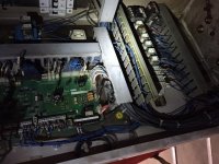
So in the past I have connected wires from output terminals 101-110, assigned M-codes to those terminals and have the wires be the medium through which 24V flows when the corresponding M-code is entered. For instance, a wire going from output terminal 101 (which has had M402 mapped to it) activates a 24V solenoid for an air blast. However, in this used machine all the wires coming from the 24V output terminals (top left in pic) go down to other ice cube relays (bottom right in pic.) Before I start tracing wires I was wondering if anyone knows what that's all about...like is it standard practice or is it more of a "who knows what the last guy was doing with that machine". The Yamazen guy figures it was used in a Honda plant due to the custom color of the machine that he says Honda paints all their machines. Thank you!
 
It looks like the IO board 24V outputs were going to the coils in the ice cube relays that were switching 220V loads. That way they could use the 24V outputs to activate 220V equipment.
 
It looks like the IO board 24V outputs were going to the coils in the ice cube relays that were switching 220V loads. That way they could use the 24V outputs to activate 220V equipment.

This method is also used if you are switching 24VDC higher current loads. The 24VDC outputs from the Brother card is limited in amperage capacity to very small loads and that is typical of most CNC/PLC output cards. If you are using larger loads, you need to put a relay between the I/O board and the load and let the relay handle the higher load.
 
The S2A has map-able inputs and outputs similar to the new Speedios. You are correct, the 51-60 terminals and 101-110 are your access. There are 8 inputs and 8 outputs available. 50 and 51 are the common and 101 and 102 are the common as I recall.

Do I need to supply 24V from somewhere to output terminals 101 / 102 in order for 103-110 to get voltage when turned on??? It's weird...with no wires going to 102 or 110 I get 24V between 102 and ground, and nothing between 102 and 110 or 110 and ground. When I turn on 110 (Via M408) I get 24 V between 102 and 110 and also between 102 and ground, but nothing between 110 and ground. I would think that with 110 on I should get 24V between 110 and ground, 24V between 102 and ground, and nothing between 102 and 110 since they would be at the same voltage potential...
 
Do I need to supply 24V from somewhere to output terminals 101 / 102 in order for 103-110 to get voltage when turned on??? It's weird...with no wires going to 102 or 110 I get 24V between 102 and ground, and nothing between 102 and 110 or 110 and ground. When I turn on 110 (Via M408) I get 24 V between 102 and 110 and also between 102 and ground, but nothing between 110 and ground. I would think that with 110 on I should get 24V between 110 and ground, 24V between 102 and ground, and nothing between 102 and 110 since they would be at the same voltage potential...

That machine is NPN.
 
thread back from the dead!

I have an S2b (2005) with the last of the a00 controls and am looking at using the (8) i/o as shown above to signal with 24v to a yukiwa rotary indexer with the ac3-10 control box. I don't have any ice cube relays as shown above. Is this machine still NPN? I guess I could just test with a fluke, but not out in the shop at the moment.

What I'm trying to figure out is the PNP wiring, as thats what the Yukiwa is setup for as well.

I have from the yukiwa and not sure where to hook up these wires:
AST-start, +24v Is this constant 24v? If so, where do I tie this into the Brother?
FIN1-block termination 1, 0v? Block termination as in ground or a block of code termination?
INCOM-input common,0v Im thinking any terminal from 51-60 for this, but direct, or with relay?
OUTCOM-output common, 24v, terminals 102-110? direct?

What terminals do I need to hook these wires up to on my brother XTI/XTO board? I think I have a good handle on the set-up side of mapping the terminals through Data Bank/User Parameters/External Input/External Output screens

I'm more trying to figure out if I need relays for the input side or directly wire these in.

What I'm envisioning is code has a M402, stops all motion/outputs a 24v signal on say terminal 110, trigger yukiwa to rotate 90 degrees, yukiwa then sends signal back on terminal 60, that triggers an M403 and brother keeps on rocking!

Thanks in advance, and Happy Thanksgiving everyone!

Already figured out some of my own questions
FN1 is an output from Yukiwa, so this should be into terminal 52-60?
AST is input to Yukiwa so this should be from terminal 103-110
INCOM should be 50 or 51?
OUTCOM should be 101 or 102?

Do these need a relay on FN1???
 
Do you have the Installation manual? There is a detailed section there on mappable IOs. I usually map an output to M21 (2nd digit is a 1). M10 will activate that output (24V between the output and common) and wait for a finish signal. Map an input to MFIN for finish signal from indexer. Run a 24VDC relay between the output and the indexer. The M10 (MDI or in your program) will provide 24V to the coil of relay and trigger the relay, hook indexer trigger input to normally open terminals on relay. When the indexing is complete, the finish output of the control box will complete the MFIN input. Be careful and I suggest studying the manual(s) or getting some help.
Happy Thanksgiving!

BrotherFrank,

Thanks for the detailed response!
I have installation manual for S2B and Yukiwa and I have to dig through them in more depth as certain info may be in one section/manual and the others in another (operators and installation manuals for the Brother for example)

Your post clarified what made sense to me having a relay on brother's output to yukiwa to isolate the load (even though it should just be a signal, not an actual load) from the brother's output board.

Where do I tap 24v that can handle a "load" from on the Brother? It surely cant just be IOG/IO24 on the IO board?
 
The load from a small relay coil should be ok (check Inst.manual) and the IO board can handle it. The outputs are terminals 103 to 110. The commons are 101 and 102 or 111 and 112 depending if it is set for npn or pnp. You can test this with volt meter. Map M21 to an output in the Data Bank. MDI M10 and check the voltage from that terminal to the commons. Reset will clear it. Installation manual has info on the hardware. Operation manual has info on the mapable choices in the Data Bank.
 
Thanks for the info in this post BrotherFrank. It has gotten me most of the way through a project I'm working on. I'm still having trouble setting an internal keep relay with a momentary button. I can see the bit change but need it to close an output. I've got a tc-s2d with a B-00 from 2010 and it came with very little documentation. The codes in the external input and output page that I can choose from are slightly cryptic without some sort of explanation. Which manual should I be looking for? Thanks
 
Thanks for the info in this post BrotherFrank. It has gotten me most of the way through a project I'm working on. I'm still having trouble setting an internal keep relay with a momentary button. I can see the bit change but need it to close an output. I've got a tc-s2d with a B-00 from 2010 and it came with very little documentation. The codes in the external input and output page that I can choose from are slightly cryptic without some sort of explanation. Which manual should I be looking for? Thanks

The Operation 'Data' manual has the details about the various mappable Inputs and Outputs. Hardware details are in the installation manual. Congrats on the S2D. That's a great machine with plenty of local support in Ohio.


Back
Top