What's new
What's new

Lathe tool data, front edge angle?

Higgins909

Aluminum
Joined
Nov 19, 2018
I'm trying to learn how to CNC, so bear with me.

Sandvik 124b f6m (DNMG)
Iscar MVJNL 12 3B K6M (VNMG)

This is what I can make out on this tooling. I can only find specs on the Iscar so far, but I don't know if it's the info I'm looking for.

It's got a -5.5 Rake angle axial and a -10.5 rake angle radial. (Don't know what these mean) In the tool setting file it ask for nose angle and front edge angle. The nose angle looks like the angle of the insert, so we got that and am having issues figuring out "Front edge angle" which in the little diagram shows the angle in between the back side of the insert I guess you can call it, and the part. Looking at the VNMG I would think it would be a lot more then 10 deg. Currently both are set to 1.0 and do work, but wonder what this really does.

Thanks,
Higgins909
 
Most of the ~standard~ tools we use are either 1 or 3° on the front.

The Nose Angle would ~I guess~ be the angle of the insert. IE VNMG=35° DNMG= 55° etc...

If they only give you the back rake angle, then back subtract the Nose Angle of the insert from the published angle. The difference is the Front Edge Angle.
 
I'm trying to learn how to CNC, so bear with me.

Sandvik 124b f6m (DNMG)
Iscar MVJNL 12 3B K6M (VNMG)

This is what I can make out on this tooling. I can only find specs on the Iscar so far, but I don't know if it's the info I'm looking for.

It's got a -5.5 Rake angle axial and a -10.5 rake angle radial. (Don't know what these mean) In the tool setting file it ask for nose angle and front edge angle. The nose angle looks like the angle of the insert, so we got that and am having issues figuring out "Front edge angle" which in the little diagram shows the angle in between the back side of the insert I guess you can call it, and the part. Looking at the VNMG I would think it would be a lot more then 10 deg. Currently both are set to 1.0 and do work, but wonder what this really does.

Thanks,
Higgins909

Assuming a Mazak? I think those angles determine whether it will be able to plunge, and/or ramp(?) angle for turning an undercut.
 
Most of the ~standard~ tools we use are either 1 or 3° on the front.

The Nose Angle would ~I guess~ be the angle of the insert. IE VNMG=35° DNMG= 55° etc...

If they only give you the back rake angle, then back subtract the Nose Angle of the insert from the published angle. The difference is the Front Edge Angle.

Yup, the front angle is more a product of the design of the holder than the insert geometry. It should be listed in the catalogue for your holder.
 
Different materials need different rake angles and clearances. Good to make a study day (or few) of this subject to make better machining, and to protect you cutting tools, parts and your machine.
 
This is on a Mitsubishi lathe, Lt-350 with NAVI conversational. It says I can input a value of 0.001 to 180.0 deg. I think Doug925 is close. In the little diagram it shows "A: Nose angle" "B: Front edge angle" B is say, you turn a part and then leave the tool there. It's the angle in between the tool and part that you just turned past. (Hopefully I'm making sense)

I'm still confused about the angles on the tool. Is the Rake angle axial or radial what I need? Looking at the sketch of the tool on Iscar's website, it looks almost 45 deg.

I don't know if there is a catalog to look (work or web) for this data. For the Sandvik I found nothing on the internet so far and so far have only been looking at the iscar as that's what I found some info for.
 
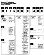
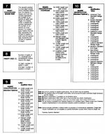
The rake angles are the tilt of the insert. Negative inserts have no clearance when sitting flat so the tool holder tilts the insert. As others have said, nose angle is more than likely the included angle of the insert. Front edge angle is the angle between x axis and the leading edge of the insert. The tool holder designation will tell you what the angle is. For your VNMG holder the J in MVJNL represents the angle. It is an ANSI standard.
 
This is on a Mitsubishi lathe, Lt-350 with NAVI conversational. (snip) It's the angle in between the tool and part that you just turned past. (Hopefully I'm making sense)

I'm still confused about the angles on the tool. Is the Rake angle axial or radial what I need?

Axial is mostly side rake (modified by approach angle = chip thinning). Side rake & back rake combine for axial rake. Is this machine estimating thrust or HP???

I’m used to end and/or side cutting angle… Attached, you’ll find “J” and the description.
Toolholders_Turning_GE1.jpg
Toolholders_Turning_GE2.jpg

Good luck,
Matt
 
By Front edge angle do you really mean side cutting edge angle? If so it is the angle of the leading edge of the insert with respect to the axis of the toolholder. You can measure it easily. (Sometimes referrer to as lead angle.)
 
When you make a toolholder there are three angles you have to get set right.
From the top view - lead angle or edge angle, how much the insert is "rotated"
Radial - holder sitting long way in front you, how much the the tool is tipped sideways, this is heel clearance or rake in the cutting direction.
Axial - holder sitting long way in front you, how much the the tool is tipped forward, this is heel clearance on the part diameter.
Should I mention the this axial and radial get flipped often? One being part view the other being holder view.

Take a square insert at 0,0,0. Not a good arrangement as the front of the insert will be flat to your diameter and chatter.
So you twist or rotate the tool say 3 degrees so the tail end is clear.
All good if a positive insert now but many inserts are negative or doublesided so you need clearance on the sides which now rub.
So you twist the insert sideways and tip it down in the front.
Since you are feeding sideways there is a sort of thread lead coming at you so you need more.
In the front when doing ODs the part falls away from your holder so you may need less rake or heel clearance.

This double negative means the back side of the tool is actually the reverse of what you want if you need to move to a smaller dia. so a profiling tool will have more rake lengthwise than would be optimal.
Also once you tip in these two planes a square is no longer a square so the top rotate or lead needs to be corrected to be off the front actual cutting side.

The standard calls out the insert lead or edge angle as if the insert was positive and setting flat, it says nothing about rakes which can and do vary with sources.
A holder for with the same letters for one company may be a tad different than the same for another.
Bob
 
The standard calls out the insert lead or edge angle as if the insert was positive and setting flat, it says nothing about rakes which can and do vary with sources.
A holder for with the same letters for one company may be a tad different than the same for another.
Bob

Ya think Bob. I was a bit confused with the 5.5 & 10.5 rakes, I just called them 5by5=10.

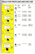
Old timey sandvik shows 27° or 30° approach with that 55° tool in the cartoons. The protractor always works...

Sandvik2.jpg

Matt


Back
Top