What's new
What's new

Machining formed (bent) plate

LostFab

Aluminum
Joined
Jul 12, 2016
Location
Cascadia, Washington
I am designing a welded steel frame that needs to have two parallel plates bow away, and then back towards each other to encompass a component. The plates are approx. 1/4" thk, 2" wide, and 12" tall, the bends are maybe 25* and add about 1" to the overall width of the structure. These brackets will need to have some machining done to lighten them up and locate a few tight tolerance bearing seats before they get welded together. The way I see it I have three options to make these parts:

1-Bend the parts from 1/4", and machine. I tried this before, it was essentially impossible to get the bends close enough to nominal geometry that I didn't end up having to machine the whole surface down a bit undersize to hit parallelism tolerance of bearing surfaces. And it ended up cracking on the bends after some testing...

2-Machine the whole part from oversized bar. Seems like a lot of chips to make, and more material expense, but the material is less likely to spring around on me.

3-Bend parts from something in between, like 3/8" where I know I will have plenty of material to remove but not hopefully too not much extra. Bend tolerances don't have to be as tight, and thicker material around the bends seems like it would mitigate the cracking issue from before as well.

Am I off my rocker thinking bending any material regardless of thickness wont totally screw this up?

Pics show the approximate geometry of the part, its still in the design process as I figure out how I want to go about making it. I did locate the critical tolerance features on the same plane this time around so I don't have to worry as much about hitting their tolerances relative to one another.
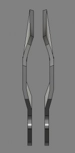
Capture1.JPG
Capture2.JPG
 
Need a bit more info, I think.

Are these parts going to be bolted to something else? Welded? In either case, being very fussy about "free air" parallelism is not productive, because they are going to move/distort when assembled.

Which surfaces of these parts are going to be bearing, and is it static or dynamic, rotating or sliding, contact? Are the "bearing seats" just bores for ball bearings (or maybe bushings)? If so, you might accomodate the assembly distortion of the frame pieces by using self-aligning bearings rather than trying to machine, pre-assembly, so that the post-assembly bore axes end up aligned. Think pillow blocks and their cousins.

What sort of flatness tolerance are we talking about? 1/16" per foot, 0.01" per 6", 0.001" per 6", 0.0002" per 6"?
What sort of profile tolerance are we talking about? ±1/32", ±0.01", ±0.001"?
 
I'd say you have two options-

Make a good tool/use good tooling to make them

or

Machine from solid.

Myself, I would make the tool. Even without having a clue what that part does it sure looks like it should be made from something much thinner with ribs formed into it to equalize stresses and add stiffness.
 
It's part of a mountain bike bike frame, it has some precision bores for suspension bearings, so the bearings seat has to be right, as does the position.

I'm not super picky about where the top ends up, I will grind or fill whatever I need to make it fit to the tube, I'm mostly just wondering about how to best use my time on a prototype. I have access to a nice brake that I ran for years so bending isn't an issue, but my experience with trying to bend to nominal and then machine the details haven't been the best..that's why I was curious about bending with stock left over. Maybe I can get the best of both worlds, or maybe it'll be the worst of both...maybe somebody out there has tried and knows its not worth the effort.
 
The weight of a MTB frame made of steel using suspension mounting plates that big will be crazy high. Just those plates will outweigh a nice entire carbon fiber frame.

Suspension bearing bores are finished after the frame is welded up on production and prototype frames. Trying to hold precise alignment of pre-finished bores while welding the rest of the frame is almost guaranteed to fail.

Right, machining tools to make a prototype carbon frame sounds like a much easier solution...
Horses for courses. Steel frames are very popular (I've made and ridden lots of them) sometimes designs just don't play well with straight tubes, and sometimes I get an itch to try something different.
 
Right, machining tools to make a prototype carbon frame sounds like a much easier solution...
Horses for courses. Steel frames are very popular (I've made and ridden lots of them) sometimes designs just don't play well with straight tubes, and sometimes I get an itch to try something different.

Machine after welding....very simple even for you to understand, but apparently you can't/won't/don't....:nutter:
 
Right, machining tools to make a prototype carbon frame sounds like a much easier solution...
Horses for courses. Steel frames are very popular (I've made and ridden lots of them) sometimes designs just don't play well with straight tubes, and sometimes I get an itch to try something different.

There's nothing wrong with steel. Your application suggests 14g, but you are planning to use 1/4 or 3/8 or was it 1/2"?
 
.....Steel frames are very popular (I've made and ridden lots of them) sometimes designs just don't play well with straight tubes, and sometimes I get an itch to try something different.

I know, I have a pair of nice old steel (one with Columbus tubing, the other Reynolds) road bikes. Was trying to point out that suspension plates that large are just wrong for a bicycle. Even if trying to call it a prototype. Thin sheet metal plate with some formed ribs for stiffness and a piece of tubing welded in for the bearing seat to be machined into would be the correct way to design something like you want. Building a prototype with thick chunky plates will not deliver the same ride characteristics just due to weight alone. It's going to feel heavy and "dead". Not the lively, resilient, almost "springy" feel of a well designed and built steel frame.
 
The reason that aluminum has become more popular than steel for suspension frames is precisely because it's easier to form complex pieces for linkages and suspension pickup points, including hydroforming tubes. It's certainly possible to do that in steel as well but clearly harder, as you need to start with thinner material. I would imagine that in 4130 steel you'd want to use something like 18Ga, or .048" at the most. As noted above, anything thicker would be heavy. That must be why most steel frames of this sort are more likely to be Ducati style bird cage designs with lots of small thin wall tubes. And, as has been said above, you definitely want to weld and then machine.
 
I know, I have a pair of nice old steel (one with Columbus tubing, the other Reynolds) road bikes. Was trying to point out that suspension plates that large are just wrong for a bicycle. Even if trying to call it a prototype. Thin sheet metal plate with some formed ribs for stiffness and a piece of tubing welded in for the bearing seat to be machined into would be the correct way to design something like you want. Building a prototype with thick chunky plates will not deliver the same ride characteristics just due to weight alone. It's going to feel heavy and "dead". Not the lively, resilient, almost "springy" feel of a well designed and built steel frame.

But with machining, you can develop the correct sizing without building tooling for different variations. Build a set, test and repeat as needed. See how many windows and lightning devices can be added.

Also, because of the bearing surfaces, there most likely will need some minor finish machining that can be done after welding.
 
...... I would imagine that in 4130 steel you'd want to use something like 18Ga, or .048" at the most. As noted above, anything thicker would be heavy. That must be why most steel frames of this sort are more likely to be Ducati style bird cage designs with lots of small thin wall tubes. .....

Yep. I was just out in the garage and measured the thickness of the formed sheet metal suspension mounting tabs on my Ducati. They are a hair over 2mm thick. Take away the paint and I'm sure they used 2mm sheet to form them from. This is on a 140+ HP, 380 pound motorcycle that can go well on the far side of 150 mph. There is absolutely no place for 2" x 12" x 1/4" thick plates on a bicycle.
 
Tubes are generally .035 to .049" wall. These parts will all get machined down to .049-.065" thick with ribs throughout, hence it being so thick to start so the ribs can be taller/stiffer.

Bearing seats are fine, using jigs and a methodical weld sequence I can maintain tight enough tolerance for smooth suspension action. IME machining the pivot locations in one solid piece is much less prone to alignment errors even after welding than sticking a bunch of separate parts together. Factories in Taiwan have more hands and hours in the day than I do so please don't tell me about how mass produced bikes are made, it is not relevant.


So to circle back to the OP...The question was not how would you build a bike, it was has anybody machined formed plate and how much can one expect it to move around/spring back after cutting.
 
".049-.065" thick with ribs throughout" is not enough information.

And I think you missed the point again. Mass produced assemblies would have the process down to where the bearing bores were pre-finished. A one-off would be finished in-situ.

Seems rather order or operations common senselike to me, but then again you're wanting to do stuff that makes no sense.

If you're going to form the metal, form the finished part. End result would be a better product.
 
Tubes are generally .035 to .049" wall. These parts will all get machined down to .049-.065" thick with ribs throughout, hence it being so thick to start so the ribs can be taller/stiffer.

Bearing seats are fine, using jigs and a methodical weld sequence I can maintain tight enough tolerance for smooth suspension action. IME machining the pivot locations in one solid piece is much less prone to alignment errors even after welding than sticking a bunch of separate parts together. Factories in Taiwan have more hands and hours in the day than I do so please don't tell me about how mass produced bikes are made, it is not relevant.


So to circle back to the OP...The question was not how would you build a bike, it was has anybody machined formed plate and how much can one expect it to move around/spring back after cutting.

Once again, machine to size.
 
I’ve machined formed plate for the purpose of bicycle frame construction and it isn’t that bad IF you have custom fixturing to maintain as rigid of a set-up as possible. Think a plate with a mirrored nest profiled into it, uniforce clamps, and then bolt on “bump” profiles to support the sections above the zero reference plane. The formed pieces absolutely need to rest on the fixture cleanly, because if you are forcing the formed pieces to conform to the fixture during clamping you’ll have a rotten time. If your formed pieces aren’t within a couple thou of each other on overall profile, you’ll have a bad time as well. And since these are effectively seatstays, you’ll need two fixture plates for the drive and non-drive sides.

You might try a machining a trough with hold down posts located inside and then pouring low temp alloy in for support instead.

Or, no offense (really), but you also might try coming up with another design. I can’t imagine how what is outlined above would yield a decent handling prototype. Yeah steel seatstays / towers run the gamut from .8 - 1.4 mm wall but they are of course round or shaped-otherwise-tubular structures which have properties fundamentally different from plate. About 10 minutes of simulation work has these as unyielding manhole covers.


Back
Top